Panel Procurement & Specification Guide
How to specify and procure IEC 61439 compliant panel assemblies.
Panel Procurement & Specification Guide
This guide explains how to specify and procure IEC 61439-compliant low-voltage switchgear and controlgear assemblies. It consolidates the standard's mandatory verifications, key rated characteristics, manufacturer practice and procurement best practices so that designers, specifiers and buyers can create unambiguous requirements and evaluate supplier responses with confidence. Where useful, the guide cites current standards and manufacturer guidance to make compliance and verification expectations explicit (see References and Further Reading).
Overview: What IEC 61439 requires
IEC 61439 governs low-voltage assemblies up to 1 000 V AC (or 1 500 V DC) and places responsibility on the assembler/manufacturer to provide a verified assembly — demonstrating compliance by a set of type tests and routine verifications rather than the older "type-tested" vs "partially type-tested" categories (the verified-assembly concept replaces those earlier terms). The standard is split into a general part (IEC 61439-1:2020) and application-specific parts (for example IEC 61439-2 for power switchgear and controlgear assemblies) that define how the general rules apply to particular assembly types (MSB, MDB, SDB, etc.) (IEC 61439-1/2) [4][5][6].
When you prepare a procurement specification reference these two parts explicitly and require the supplier to provide the verification report and test certificates for the exact product configuration offered.
Key electrical and mechanical characteristics to specify
At minimum, a clear IEC 61439 procurement specification should state the following rated characteristics and verification expectations. Each item also links to the clause or common practice where relevant.
- Rated voltages — rated operational voltage (Un), rated insulation voltage (Ui) and rated impulse withstand voltage (Uimp). For many LV assemblies Ui ranges up to 690 V and Uimp values of 6–12 kV are common (Table 2.2 in IEC 61439) — for example Uimp = 12 kV where Ui is 300–690 V [4][5].
- Short-circuit withstand (Icw and related values) — dynamic and thermal strength must be verified. Typical commercial products show Icw ratings from tens of kA up to 150 kA for heavy-duty lines; smaller assembly sections (≤630 A busbars) are commonly verified to Icw values up to ~35 kA in standard type tests, while factory-verified systems from major vendors can reach 50–150 kA depending on design and fault duration [2][3][4].
- Temperature-rise limits and ambient — temperature-rise testing uses a reference ambient of ≤35 °C. Assemblies must meet rated current without exceeding the specified temperature-rise limits per the type test and acceptable continuity of circuit performance, factoring rated diversity where relevant (RDF) [1][2][4].
- Dielectric properties and clearances/creepage — power-frequency withstand voltage and impulse withstand limits are mandatory; as an example power-frequency withstand for Ui = 300–690 V requires ~1 890 V AC for 1 s in the type test, and impulse withstand values align with the chosen Uimp (see IEC 61439 clauses for test values and Table 2.2) [1][2][3]. Clause references include 10.9–10.11 for dielectric testing and clearances/creepage verification.
- Degree of protection (IP) and mechanical — specify the required IP rating (IP31–IP55 are typical for LV assemblies) and note that mechanical IK ratings are not usually applied to power switchgear assemblies; the glow-wire test requirements and short-circuit strength of protective circuits are covered in the standard (see clauses on IP and mechanical/thermal protection) [1][2][3].
- Protection against electric shock and earthing — verify continuity to protective earth (resistance measurements), short-circuit strength of protective circuits and the IP/IEC protections against direct contact (e.g., IPXXB and associated tests) [1][2].
- Neutral conductor rules — neutral cross-sectional sizing: the neutral should have 100% of the phase conductor cross-section up to 16 mm²; above 16 mm² it may be 50% of phase cross-section but never smaller than 16 mm² (and larger for non-copper conductors) [1].
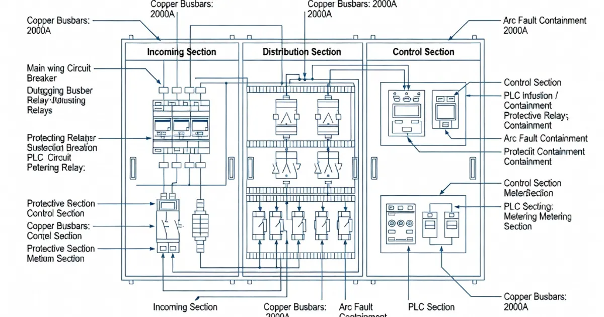
- Internal separation forms — define the required form of internal separation (Forms 1 through 5 as per IEC 61439-2) appropriate for equipment accessibility and safety (e.g., Form 2b, 3b, 4b are commonly requested for commercial switchgear) [5].
- Conductor installation limits — specify allowable lengths of non-protected live conductors between busbar and the first SCPD (service control protective device). IEC 61439 limits unprotected conductor lengths (commonly ≤3 m for many installations, see Table 4) to reduce risk and ensure correct operation of protective devices [4].
Verification: the mandatory type tests and constructional checks
IEC 61439 requires a combination of type tests (performed once on a prototype family or series) and routine or production verifications. The standard defines seven main type tests that a verified assembly must pass, plus constructional checks and required routine verifications. The typical list is:
- Temperature-rise test — verifies allowable temperature rise at rated current and under specified RDF conditions.
- Dielectric tests — power-frequency and impulse withstand tests, plus verification of clearances and creepage distances.
- Short-circuit (electrodynamic and thermal) test — demonstrates structural and contact integrity under design fault currents.
- Verification of protective circuit — continuity and short-circuit strength of protective earth and protective conductor arrangements (resistance measurement to PE terminal).
- Verification of clearances and creepage — design verification to ensure adequate dielectric separation for the declared Ui and Uimp.
- Mechanical operation — mechanical endurance and correct operation of moving parts and switching devices under load cycles.
- Degree of protection (IP) test — verifies that the assembly meets the declared enclosure protection level (e.g., IP31–IP55) [2][5][1].
Additionally, manufacturers must perform constructional verifications (review of drawings, component selection, mechanical and electrical integration) and routine verifications on each delivered assembly (such as dielectric and continuity checks where required). Request the full verification report and certificates as part of procurement documentation [5][2].
Practical procurement checklist for specifiers
Include the following items in the procurement documentation and require suppliers to attach corresponding evidence:
- Declared rated values: Un, Ui, Uimp, rated frequency (typically 50 Hz), rated currents for busbars and outgoing circuits.
- Declared short-circuit ratings: rated short-circuit making current (Icm), rated ultimate short-circuit breaking capacity, rated short-time withstand current (Icw) and the duration (e.g., 1 s, 3 s) — require type test certificates showing the values and test conditions [4][5].
- IP rating and test certificates for the specified enclosure protection (e.g., IP43/IP54/IP55) and confirmation of glow-wire/fire resistance testing where applicable [1][3].
- Form of separation required (1–5) and internal layouts/drawings showing segregation between busbar, incoming, outgoing and cable compartments [5].
- Manufacturer's verification report demonstrating that the specific configuration delivered is covered by a type-tested or otherwise verified family (include test reports, serial numbers, drawings and factory acceptance test results) [5][6].
- Routine test list to be performed at delivery (e.g., insulation resistance, continuity to PE, functional operation of SCPDs).
- Ambient and installation conditions: specify design ambient (35 °C typical), altitude derating if required and other site-specific constraints [4].
- Neutral and PE sizing and bonding requirements (state minimum cross-sections and maximum PE resistance target — e.g., PE < 0.1 Ω for critical systems) [1].
- Installation clearances, maximum non-protected conductor lengths (e.g., ≤3 m between busbar and SCPD where applicable) and routing/labeling requirements [4].
- Factory acceptance test (FAT) and optional site acceptance test (SAT) scope, witness rights, and documentation handover (drawings, BOM, test certificates, maintenance instructions) [5][6].
Manufacturer capability: examples and typical ranges
Major switchgear manufacturers publish verified assembly lines and datasheets that provide quick reference values for common procurement cases. The following table compares representative vendor claims and typical specification ranges encountered in industry literature and vendor documentation. Use this table for orientation only — always require the supplier to produce the specific verification documentation for the exact configuration offered.
| Brand | Product / Line | Representative Icw range | Typical IP / Forms | Ui / Uimp (typical) |
|---|---|---|---|---|
| Siemens | NXPLUS, SIVACON families | up to 50 kA (vendor lines vary by cell) | IP43–IP55; forms 2b–4b | Ui 690 V; Uimp 12 kV |
| ABB | UniGear / System pro E | ~50–100 kA (range by series) | IP31–IP54; forms 1–4 | Ui 400–690 V; Uimp up to 12 kV |
| Schneider Electric | Okken, PrismaSe | 36–150 kA (depending on design) | IP30–IP54; forms 1–4a | Ui 400–690 V; Uimp 6–12 kV |
| Eaton | Power Xpert / ModCell | ~50–100 kA | IP31–IP55; modular cells | Ui up to 690 V; Uimp up to 12 kV |
| Rittal | Perforex / Ri4Power | Busbar and cell-specific ratings up to tens of kA | IP55 options; compact cells | Ui up to 690 V; Uimp 6–12 kV |
These vendor ranges match typical industry practice: verified assemblies for commercial and industrial switchgear commonly provide IP in the IP31–IP55 range, Icw from tens to hundreds of kA depending on design and duration, and Ui / Uimp values that conform to Table 2.2 of IEC 61439 [3][4][6]. Always require the supplier to confirm the duration used for Icw (for example 1 s or 3 s) and whether the value is symmetrical or asymmetrical.
Design and installation best practices
Follow these practical rules to reduce risk and speed approval:
- Prefer fully type-tested / verified lines — using an existing verified assembly family reduces the amount of site-specific calculation and the risk of incomplete verification for bespoke configurations [5][6].
Related Panel Types
Frequently Asked Questions
Request a Quote
Tell us about your panel requirements and our engineering team will get back to you within 24 hours.
Email Us
[email protected]Call Us
+90 232 332 22 78