Panel Installation Best Practices
Site installation procedures and requirements for panel assemblies.
Panel Installation Best Practices
Successful installation of low-voltage switchgear and controlgear assemblies requires strict alignment with IEC standards, careful site planning, and disciplined execution. This guide consolidates IEC requirements and manufacturer practices into a practical, standards-based checklist for installers, commissioning engineers, and project managers. It references IEC clauses and manufacturer guidance to help you minimize risk, ensure electrical performance, and facilitate safe operation and maintenance.
Overview: Standards and Verification Routes
IEC 61439 (parts 1 and 2) defines the rules for low-voltage switchgear and controlgear assemblies (Un ≤ 1 000 V AC / 1 500 V DC). It prescribes three equivalent verification routes for an assembly’s capabilities: testing, calculation, or comparison to a type-tested design. Per IEC 61439-1 (ed. 2020) the assembler must demonstrate compliance for electrical, thermal, dielectric, and mechanical requirements through one of these methods (testing, calculation, comparison) and document the results for the as-installed configuration (see IEC 61439-1 Clause 4 and Clause 10) [IEC 61439-1 references in the ABB workbook and Hager guide].
Key complementary standards used for installation and performance considerations include:
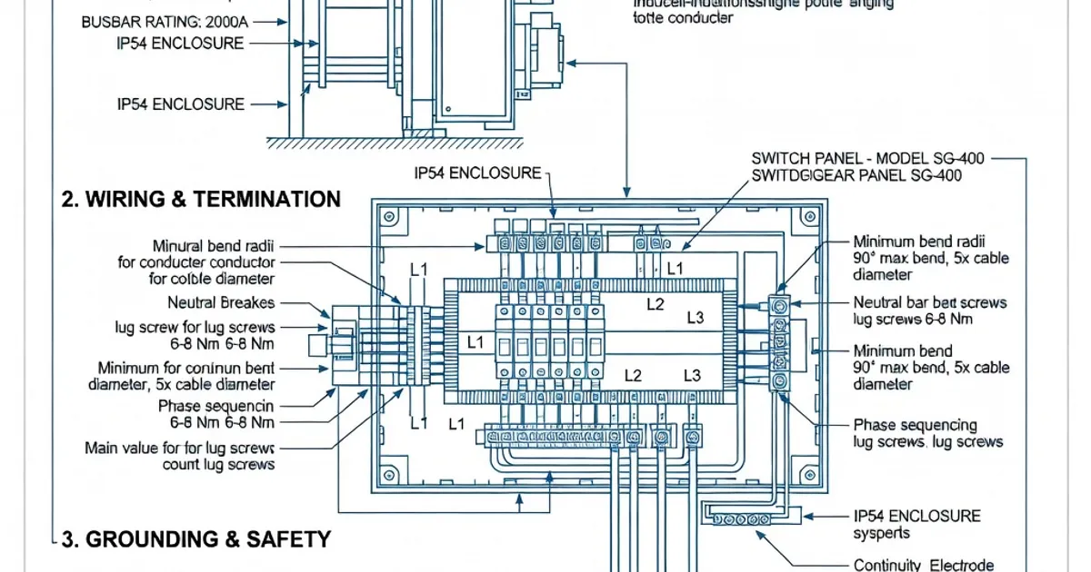
- IEC 60529 — degrees of protection (IP ratings) for enclosures.
- IEC 60364-7-729 — application rules that inform minimum operating and maintenance corridor widths and access clearances.
- IEC TR 61641 — guidance and test practice for arcing faults and arc fault containment and pressure relief.
- IEC 60947 series — requirements for the circuit-breakers and other LV switching components used inside assemblies.
Practical manufacturer guides (ABB, Hager, etc.) apply these standards to product-specific installation instructions; installers must adhere to both the standard and the equipment manufacturer’s guidance for the specific panel model [see ABB workbook; Hager guide].
Pre-installation Planning
Plan the installation using documented environmental conditions, expected short-circuit levels, load currents, harmonic content, and physical constraints. Key pre-checks include:
- Confirm the panel’s type-test/verification method (tested, calculated, or compared). Ensure documentation is available on-site (verification reports, measurement certificates) as required by IEC 61439-1.
- Determine the site ambient temperature and altitude. Per IEC 61439-1 Clause 6.1, rated thermal performance assumes a reference ambient (commonly 35 °C or 40 °C); apply manufacturer derating where site ambient exceeds this [see ABB workbook and Viox summary].
- Obtain the site short-circuit prospective current (SCC). Verify the panel’s rated short-time withstand (Icw) and peak current meet or exceed the site prospective values — include arcing considerations per IEC TR 61641.
- Plan cable routing early to avoid unprotected live conductor runs > 3 m between the main busbar and a short-circuit protective device (SCPD), as limited by IEC 61439-1 Clause 8.6.1–8.6.2.
- Check the floor structure and anchor locations: floor-standing assemblies often require vibration-free, level concrete plinths sized and rated per manufacturer instructions.
Clearances, Access, and Working Space
Maintain minimum clearances for safe operation, cooling, and maintenance. IEC-related guidance and installation guides converge on these practical minima:
- Front operating clearance: typically 1.0–1.2 m for operation (sufficient for access to controls and visual inspection). For maintenance tasks involving removal of covers or cable work, provide additional clear working space; some manufacturers recommend 800 mm–1 200 mm clear in front and 600 mm at the rear for cable work [IEC 60364-7-729; electrical-engineering-portal guidance].
- Side clearances: manufacturers commonly specify 100–200 mm minimum to allow ventilation and heat dissipation; larger spacing may be required for cable access or to meet IP and segregation requirements (see product installation manuals from Siemens, Schneider, and ABB).
- Top clearance: leave adequate space for heat stratification, outgoing cable bends, or installed fans/exhausts — follow manufacturer’s envelope dimensions precisely.
These clearances ensure safe operator access and reduce overheating risks. Plan corridors and service routes in the building design stage and reflect them in the project drawings (cage dimensions, removal zones, door swing, and lifting clearances).
Degree of Protection (IP Rating) and Environmental Considerations
Select an enclosure with the appropriate IP rating for the installation environment per IEC 60529:
- Indoor commercial/industrial: IP31 to IP43 is commonly acceptable for clean, dry indoor environments with limited exposure to water. Many LV panels are supplied as IP31 or IP43 with optional IP54/55 kits for doors and venting [see Hager and ABB product literature].
- Aggressive or dusty environments, wet areas, or outdoor locations: select IP54 or IP55 and anti-corrosion coatings/materials; consider stainless steel or special surface treatments and confirm ingress protection after installation (seals, cable entries, and conduit glands must be IP-rated).
- Ambient temperature: IEC 61439-1 Clause 6.1 sets reference conditions. Panels are typically rated for operation up to 35–40 °C average; above that apply manufacturer-specified derating factors for busbars, protective devices, and cable ampacity [ABB workbook; Viox guide].
When specifying panels, document the intended ambient, altitude, humidity class, and corrosivity so the manufacturer can supply the correct enclosure variant and components.
Earthing, Protective Measures, and Conductor Length Limits
Proper earthing and conductor routing prevent unacceptable touch voltages and limit damage in the event of short-circuits. Key rules:
- Equipotential bonding and main earthing conductor sizing and routing must follow IEC 61439-1 (clauses 8.6.1–8.6.2) and local wiring rules. Use continuous conductors and minimize joints where possible.
- Limit unprotected live conductor runs to 3 m maximum between the main busbar and the first SCPD or the point where protection is provided, per IEC 61439-1 clauses; longer runs increase the risk of severe fault energy and make verification of short-circuit withstand more complex [ABB workbook].
- Provide adequate earth fault loop impedance to ensure protective devices clear faults within their operating times. Verify with on-site loop impedance measurements at commissioning.
Document earthing conductor size, routing, lug tightening torques, and any supplementary equipotential bonding arrangements in the electrical installation record.
Short-Circuit Withstand and Arc Fault Considerations
Design for the site’s prospective short-circuit power. The assembly’s rated short-time withstand (Icw) and peak current must be established by test, calculation, or comparison per IEC 61439-1 and IEC 61439-2.
- Typical Icw ratings for mainstream factory-tested panels range from 35 kA to 150 kA (1 s or 3 s periods depending on product). Some heavy-duty power switchgear assemblies are type-tested at higher levels (e.g., up to 150 kA) [manufacturer datasheets].
- Include arc fault mitigation: IEC TR 61641 gives guidance on designing for arcing faults — pressure-relief paths, mechanical retention, barriers, and arc containment are part of the panel design and must be validated for the expected arcing energy on site [IEC TR 61641; product arc-test declarations such as Eaton and Rittal].
- For sites with very high prospective faults, coordinate series-limiting devices (fuses, upstream breakers), busbar cross-sections, and mechanical reinforcement to ensure both thermal and electromechanical integrity.
Thermal Performance and Temperature Rise
IEC 61439-1 Clause 10.10 sets maximum allowable temperature rises for terminals, busbars, and other current-carrying parts. Verify the as-built assembly by one of the three verification routes:
- Type testing: thermal tests at rated currents to confirm temperature rises are within limits.
- Calculation: validated thermal models using component resistances, connection resistances, ventilation, and ambient to estimate temperature rise.
- Comparison: use a similar type-tested assembly and apply correction factors for the differences.
Practical items to control thermal risk on-site:
- Ensure tight torque on screw and bolted connections — loose connections create hot spots. Use calibrated torque tools and record torques in commissioning records.
- Provide manufacturer-specified ventilation, fan circuits, or cooling units as required for high load densities or high ambient temperatures; verify airflow and filter cleanliness for ventilated enclosures.
- Consider harmonics and nonlinear loads; harmonic currents increase conductor heating and may require oversizing of neutral conductors and derating of protective devices.
Mechanical Installation: Mounting, Weight, and Handling
Follow manufacturer guidance on anchoring, floor loading, and lifting:
- Floor-standing switchgear usually requires a level, vibration-free concrete base sized to the panel’s footprint and weight. Manufacturers often specify anchor bolt positions and recommended baseplate clearance for cable entry and drainage [see Rittal and Siemens installation guides].
- Wall-mounted panels must be mounted to a structure capable of supporting the panel mass plus dynamic loads during door operation and maintenance tasks. Verify wall fixings and use recommended mounting kits.
- When multiple panels are aligned, install the first unit plumb and square; use shims and alignment brackets to maintain uniform busbar heights and door gaps for consistent IP performance across the row.
Cable Routing, Termination, and Conductor Selection
Plan cable entries and segregation to satisfy thermal, electrical, and safety requirements:
- Use separate compartments for power and control wiring where the panel form of separation requires it (e.g., forms 2, 3b, 4b depending on manufacturer and application), and maintain segregation inside the panel according to the declared form of separation and manufacturer layout [Hager guide].
- Size cables using the actual installation ambient, grouping, and permissible temperature rises. Apply derating factors if cables are bunched or enclosed in trays within the panel.
- Terminate conductors on appropriately sized terminals and torque to manufacturer values. Mark cable identification clearly and route cables to minimize bend radii and stress on terminations.
Factory-Assembled vs Field-Built Panels
Factory-assembled, type-tested assemblies minimize on-site risk versus field-built switchboard assemblies. Advantages include:
- Complete factory verification (thermal, dielectric, short-circuit) reduces the need for extensive on-site testing and reduces variability introduced by site workmanship.
- Manufacturer quality control and traceable components improve longevity and simplify documentation for compliance with IEC 61439-1/2.
When field assembly is necessary, follow a strict factory test comparison approach or perform the required tests on the final assembly; document workmanship, torque records, and site test results per IEC 61439-1 requirements.
Commissioning and Site Tests
Commissioning must confirm the installation matches the declared configuration and that performance meets the verification method. Typical commissioning tests include:
- Continuity and insulation resistance tests of circuits and protective conductors.
- Torque verification on all power connections and documentation of torque values.
- Loop impedance/earth-fault tests at relevant points to verify protective device clearing times.
- Functional testing of protection coordination (overcurrent, ground-fault, and residual current devices).
- Thermal imaging after initial load run-in to detect hot spots.
Retain and hand over a complete commissioning dossier: wiring diagrams, as-built drawings, component certificates, verification/calculation reports, torque records, and test results as required by IEC 61439-1 documentation rules.
Maintenance and Operational Best Practices
Planned maintenance reduces risk from loose connections, dust, and component degradation:
- Schedule periodic cleaning, inspection of seals (for IP-rated enclosures), and replacement of filters on ventilated cabinets.
- Maintain torque checks on accessible terminals after the first season of thermal cycling and at planned intervals thereafter.
- Record all changes to the assembly (additions, busbar changes, feeder reconfiguration) and re-evaluate the assembly against the original verification route if changes affect current-carrying capacity or short-circuit performance.
Manufacturer Examples and Typical Installation Specs
Major manufacturers publish product-level installation guides that detail clearances, IP ratings, and test ratings. Below is a condensed comparison of common product characteristics taken from manufacturer literature and practical implementations: