IEC 61439 vs IEC 60439: Key Differences
Comparison between the current IEC 61439 and former IEC 60439 standards for panel assemblies.
IEC 61439 vs IEC 60439: Key Differences
This article explains the practical and technical differences between IEC 61439 (the current series for low-voltage switchgear and controlgear assemblies) and the superseded IEC 60439. It clarifies the new verification philosophy, key performance requirements (temperature rise, short‑circuit withstand, degree of protection, mechanical strength), and the consequences for designers, manufacturers and specifiers. The content consolidates official clauses, industry guidance and manufacturer practice so you can apply IEC 61439 requirements with confidence in panel design and certification.
Overview: Why IEC 61439 replaced IEC 60439
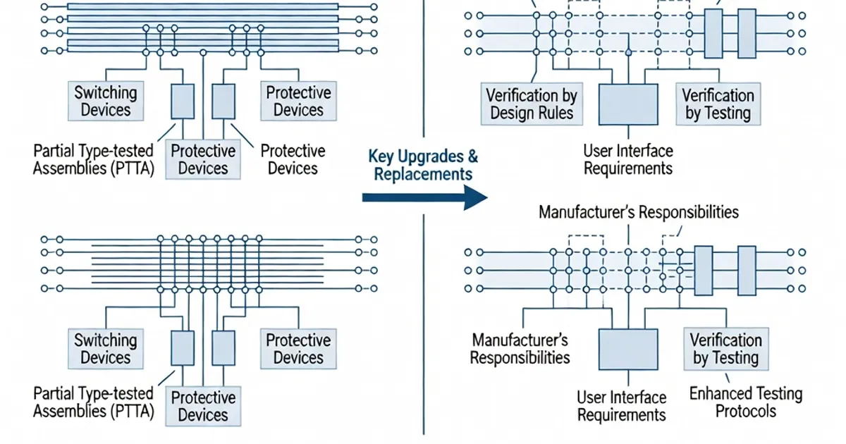
IEC 61439, published in its first edition in 2009 and maintained with updates (e.g. IEC 61439-1:2020 Ed.3.0), replaced IEC 60439 to address the limitations of a test regime that treated assemblies as either fully type tested (TTA) or partially type tested (PTTA). The older binary approach often proved inflexible for modular systems, kit-based assemblies and custom builds. IEC 61439 replaces the TTA/PTTA dichotomy with a performance‑based verification approach that applies to all assemblies and focuses on the assembly as a whole rather than duplicating device‑level tests from product standards (e.g., IEC 60947 series) (see IEC 61439-1 and supporting industry guidance).
IEC 61439 applies to low-voltage switchgear and controlgear assemblies up to 1 kV AC / 1.5 kV DC and integrates construction rules from IEC 62208 for empty enclosures. The standard provides three equivalent verification routes (testing, calculation/measurement, or design rules) so manufacturers can choose the most economical and technically appropriate method for each duty (per IEC 61439-1 Clauses 4–11).
Core Change: Verification by Design Instead of Fixed TTA/PTTA Labels
IEC 61439 eliminates the rigid Type Tested Assembly (TTA) and Partially Type Tested Assembly (PTTA) definitions used under IEC 60439. Instead, it requires that the assembly’s performance be verified by one of three equivalent methods:
- Verification by testing — prototype tests to the required performance levels (e.g., short-circuit, temperature rise).
- Verification by calculation and measurement — validated analytical methods and measurements for parameters such as busbar temperature rise and short-circuit forces.
- Verification by satisfying design rules — following prescribed construction rules and manufacturer design rules that are known to achieve the required performance.
All three methods are equivalent under IEC 61439-1 and must be documented in a verification dossier (see Clause 11) so the performance can be traced, audited and repeated for production variants.
Key Technical Differences and Clause References
Scope and Application
IEC 61439 applies to the same application envelope (up to 1 kV AC / 1.5 kV DC) as IEC 60439 but expands clarity on modular and kit-based assemblies, internal separations, and interfaces with product standards (e.g., IEC 60947). The general rules are given in IEC 61439-1, with application-specific requirements in the relevant parts (e.g., 61439-2 for power switchgear and controlgear assemblies) (see IEC 61439-1 and IEC 61439-2).
Temperature Rise Verification (IEC 61439-1 Clause 10.10)
IEC 61439 refines temperature rise rules and the way rated current is determined for assemblies:
- Terminal temperature rise limits are clarified: the standard uses reference limits such as 70 K average and 105 K maximum at terminals for certain conditions (see Clause 10.10 for precise measurement points and averaging rules).
- Rated current is attributed to the assembly based on the assembly performance — not simply the device nameplate — and must account for busbar heating, connections and thermal interaction between devices.
- The standard explicitly recognises the use of a Rated Diversity Factor (RDF) when calculating assembly temperature rise for multiple outgoing circuits; designers must justify RDF values and include them in the verification dossier (see Clause 5.4 and Clause 10.10).
Per IEC 61439-1 Clause 10.10, temperature-rise verification may be performed by test, calculation or by use of validated design rules — allowing manufacturers to test a prototype and use calculation methods for production variants.
Short-Circuit Withstand Strength (IEC 61439-1 Clause 10.9)
IEC 61439 retains the need to verify short‑circuit withstand strength, but expands the ways that verification may be demonstrated:
- Dynamic and thermal stresses from short-circuit currents must be assessed for the complete assembly, including busbar supports, connections and enclosures.
- Verification can be achieved by full-scale testing, validated calculation methods (electrodynamic and thermal), or compliance with manufacturer design rules that demonstrate equivalent withstand capability (Clause 10.9).
- Testing levels and SCCR values (e.g., 50 kA, 100 kA) are defined per the application and selection; manufacturers such as ABB and Siemens publish short-circuit performance for products (e.g., MNS up to 100 kA SCCR, Siemens SIVACON series with 40.5 kA levels) as part of their verification strategies.
Degree of Protection (IEC 61439-1 Clause 10.11)
IEC 61439 aligns enclosure protection requirements with IEC 60529 (IP codes) and clarifies how IP ratings apply to assemblies and individual compartments. Designers must specify required IP levels up front in the duties/annex so verification focuses on the intended operating environment rather than generic claims (per IEC 61439-1 Clause 10.11).
Internal Separation, Clearances and Mechanical Strength (Clauses 10.5, 10.7 and related)
IEC 61439 includes stricter and more explicit rules for internal separation (forms of separation 1–4b), creepage distances, clearances and mechanical endurance:
- Form of separation must be specified and verified (e.g., Form 3b or Form 4b for high-availability, arc-mitigation applications). IEC 61439-2 provides additional guidance for power assemblies.
- IEC 61439 prescribes mechanical endurance tests, including a 200‑operation mechanical test for certain moving parts and interlocks (see Clause 10.7).
- Creepage and clearance distances follow the harmonised rules, and empty enclosure rules from IEC 62208 are incorporated to cover enclosures intended for use in assemblies (IEC 61439-1 Clause 10 and Annexes).
Documentation and Traceability (Verification Dossier — Clause 11)
IEC 61439 requires production of a verification dossier that records the verification route, test reports, calculation files, design-rule justifications, RDF assumptions and traceability of critical components. The dossier must enable repeatability and prove that production assemblies match the verified design. This represents a decisive improvement over IEC 60439 practice where traceability and documentation were often incomplete.
Comparison Table: IEC 60439 vs IEC 61439 (High-level)
| Aspect | IEC 60439 (legacy) | IEC 61439 (current) |
|---|---|---|
| Verification approach | Binary TTA / PTTA classification with rigid test requirements | Three equivalent verification methods: testing, calculation/measurement, or design rules; verification dossier required (IEC 61439-1) |
| Rated current attribution | Often based on device nameplate or TTA result | Based on assembly performance accounting for busbar heating, connections and RDF (IEC 61439-1 Clause 10.10) |
| Temperature rise limits | Prescriptive test limits, less clarity for modular kits | Clear limits and measurement points (e.g., terminal avg 70 K / max 105 K); allows calculation or design rules (Clause 10.10) |
| Short-circuit verification | Full-scale tests customary for TTA; PTTA partial testing | Test, calculation or rule‑based verification for dynamic/thermal stresses (Clause 10.9) |
| Form of separation / enclosure rules | Present but less integrated with enclosure standards | Integrated with IEC 62208; explicit separation forms and mechanical tests (Clauses 10.5, 10.7) |
| Documentation | Variable; not consistently required | Mandatory verification dossier documenting method, results and traceability (Clause 11) |
Implications for Manufacturers, Integrators and Specifiers
IEC 61439 changes behaviour across the supply chain. Manufacturers and integrators gain flexibility: they can certify a prototype and then apply validated calculations or prescriptive design rules to variant builds, reducing the need to perform full-scale tests for every configuration. Specifiers must state the assembly duties early (IP, rated current, separation form, short-circuit rating, operating temperature, etc.) so manufacturers can select the most economic verification route.
- Designers should use the annexes in IEC 61439-1 and the part-specific Clauses (e.g., IEC 61439-2) to set duties and limits before detailed design (BEAMA guidance recommends this practice).
- Use of RDF must be justified and recorded. Clause 5.4 and Clause 10.10 detail how diversity affects rated current and temperature rise calculations.
- Legacy 60439 panels require re-evaluation when substantial changes occur; the industry initially saw low full compliance in some markets (e.g., a small percentage of UK panels were compliant at early transition stages), but large manufacturers now base product ranges on IEC 61439 verification methods (see Quantum Controls and BEAMA summaries).
Technical and Commercial Best Practices
Industry experience and guidance from BEAMA, ABB and manufacturers suggest the following practical steps when transitioning to or designing for IEC 61439:
- Define the duty up front: Specify rated operational current, IP, form of separation, short-circuit rating and environmental conditions in the project specification or in the assembly annex (per IEC 61439-1 Annex guidance).
- Choose verification routes wisely: Test a representative prototype for structural or short-circuit extremes and use validated calculations or design rules for similar variants to reduce test costs (this hybrid approach is common among major suppliers).
- Document RDF and calculation assumptions: Record diversity factors, load patterns and thermal interactions in the verification dossier per Clause 11.
- Follow enclosure guidance: Apply IEC 62208 construction rules for empty enclosures and use IEC 60529 for IP ratings to avoid mismatched protection claims (IEC 61439-1 Clause 10.11).
- Consider form of separation carefully: For critical switchboards or MCCs, select Form 3b/4b where necessary and ensure verification covers arc fault and clearances.
- Maintain traceability: Keep a complete verification dossier including test reports, calculation files, component certificates (e.g., busbars, circuit-breakers per IEC 60947) and manufacturing change controls.
Product Examples and Industry Practice
Major manufacturers illustrate how IEC 61439 verification is implemented in commercial products:
- Siemens documents differences between 60439 and 61439 and applies the IEC 61439 verification approach to product lines such as SIVACON and NXPLUS C, publishing short-circuit ratings, enclosure IP and verification methods in technical manuals (see Siemens application notes).
- ABB uses the IEC 61439 framework for its MNS family and provides technical papers that describe how MNS achieves required thermal and short-circuit performance through combined testing and calculation (ABB INTCB-LS04 paper).
- Schneider Electric, Eaton and Rittal provide modular kit systems with design rules and software tools (e.g., thermal/short-circuit calculators) to enable verification by calculation and design‑rule compliance, lowering the per-unit cost of verification for custom panels.
Manufacturers therefore offer both tested assemblies and validated design kits which allow integrators to assemble compliant switchboards without repeating full‑scale type tests. This has reduced test costs for kit-based assemblies by an industry‑reported 50–70% in many cases, while ensuring compliance through documented verification routes (industry white papers and manufacturer guides).
Transition, Compliance and Auditing
Transitioning from IEC 60439 to IEC 61439 requires careful handling of existing products and documentation:
- Existing 60439 TTA/PTTA certificates do not automatically equate to IEC 61439 compliance. Where a 60439 assembly remains unchanged, organisations should produce a verification dossier under IEC 61439 principles or re-verify if modifications occur.
- Regulatory markets using EN 61439 (the European Harmonised standard) tie compliance to the Low Voltage Directive; confirm national transposition and CE/UKCA marking requirements for assemblies intended for sale in these markets.
- Auditors and customers increasingly request the verification dossier as evidence of compliance. Clause 11 of IEC 61439-1 outlines the dossier content and the evidence required for each verification route.
Practical Example: Temperature Rise Calculation and RDF
When sizing a multi-outgoing distribution board, engineers must account for the Rated Diversity Factor (RDF). IEC 61439 allows application of RDF in temperature rise calculations
Related Panel Types
Frequently Asked Questions
Request a Quote
Tell us about your panel requirements and our engineering team will get back to you within 24 hours.
Email Us
[email protected]Call Us
+90 232 332 22 78