Design Verification Methods in IEC 61439
The three design verification methods: testing, calculation, and design rules explained.
Design Verification Methods in IEC 61439
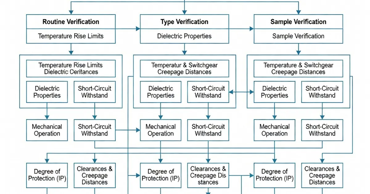
IEC 61439 establishes a structured, auditable framework to verify performance of low-voltage switchgear and controlgear assemblies (LVSAs). The standard recognizes three equivalent routes to demonstrate compliance with the functional and safety characteristics of an assembly: verification by testing, verification by comparison with a tested reference design, and verification by assessment using calculations and documented design rules with prescribed safety margins. These methods address key performance areas such as temperature rise, short-circuit withstand, dielectric behaviour and mechanical strength, and are collated in Annex D (Table D.1) of IEC 61439‑1:2020 [Per IEC 61439‑1 Annex D, Table D.1][3][4].
Why Multiple Verification Routes?
IEC 61439 provides multiple, equivalent verification routes to balance safety, repeatability and industrial scalability. Full testing gives the highest confidence for a specific assembly configuration. Comparison and assessment permit manufacturers to extend a tested design across product variants (e.g., different enclosure sizes, busbar lengths, device combinations) while controlling cost and time. The standard requires transparent documentation and conservative margins when reducing direct testing to preserve the safety envelope established by full-scale tests [Per IEC 61439‑1 Clauses 10.5–10.6; Annex D][1][2][4].
Summary of the Three Verification Methods
- Verification by testing — Perform full, type tests on a representative sample assembly. Tests include temperature-rise, dielectric, and short-circuit withstand per the relevant clauses (e.g., temperature rise Clause 10.10, dielectric Clause 10.9, short-circuit Clause 10.11) [Per IEC 61439‑1 Clauses 10.9–10.11][2][4].
- Verification by comparison — Demonstrate equivalence to a tested reference assembly by structured comparison and documented justification (Clause 10.5 and Annex C). This method is used widely to derive ratings for functionally similar circuits or alternative component arrangements [Per IEC 61439‑1 Clause 10.5; Annex C][1][2][4].
- Verification by assessment — Use calculations and prescriptive design rules (Clauses 10.6, Annexes D and P) with mandated safety margins (for example +50% for certain dielectric values) to establish compliance without retesting every variant [Per IEC 61439‑1 Clause 10.6; Annex P][1][2][4].
Allowed Methods by Characteristic
| Characteristic | Testing | Comparison | Assessment | Reference Clause |
|---|---|---|---|---|
| Temperature rise | ✓ | ✓ | ✓ | Clause 10.10 [2][4] |
| Short-circuit withstand | ✓ | ✓ | ✗ | Clause 10.11 [1][4] |
| Dielectric properties (impulse/PF/DC) | ✓ | ✓ | ✓ (+50% margin where required) | Clause 10.9 [2] |
| Mechanical strength | ✓ | ✓ | ✓ | Clause 10.7 [1] |
Detailed View: Verification by Testing
Verification by testing remains the definitive route and the preferred approach in many cases because it provides direct measurement of the assembly’s behaviour under defined conditions. IEC 61439-1 defines the test types, sample representativeness and acceptance criteria. Key test categories include:
- Temperature-rise tests (Clause 10.10): Measure conductor and enclosure temperature increases under rated current conditions or specified test currents to ensure the assembly limits are not exceeded. These tests verify busbar heating, terminal connections and thermal interaction across functional units [Per IEC 61439‑1 Clause 10.10][2][4].
- Short-circuit withstand tests (Clause 10.11): Apply prospective fault currents to verify electrodynamic and thermal withstand of busbars, connections and supporting structures. These tests validate assembly integrity under fault conditions; short-circuit testing is mandatory where assessment is not permitted for the characteristic [Per IEC 61439‑1 Clause 10.11][1][4].
- Dielectric tests (Clause 10.9): Verify clearances, creepage distances and insulation systems using power-frequency, impulse and DC tests where applicable. The standard prescribes test voltages and procedures and permits certain assessment substitutions with conservative margins [Per IEC 61439‑1 Clause 10.9][2].
- Protection and ingress (IP) verification: Confirm protection degrees in accordance with IEC 60529 when required and as part of routine verification of manufactured units [IEC 60529][3].
Manufacturers choose representative samples to cover the most onerous configuration — e.g., the highest rated busbar layout, maximum conductor groupings, heaviest device fitment — and perform full sequence tests. Routine verifications (Clause 11) then complement type testing to control workmanship and production quality [Per IEC 61439‑1 Clause 11][3].
Verification by Comparison (Reference Design)
Comparison allows a manufacturer to claim compliance for an assembly variant based on documented equivalence to a tested reference assembly. IEC 61439-1 requires a structured comparison (Clause 10.5, Annex C) that records all relevant differences and shows they do not degrade the characteristic under consideration. Typical use-cases include:
- Deriving ratings for thermally similar circuits: when busbar geometry, material and current distribution remain within defined limits, outgoing circuits may inherit ratings from the tested reference.
- Using a tested functional unit (e.g., a compartment with a particular device arrangement) as a reference for similar compartments in other assemblies.
- Applying tested subassemblies (e.g., busbar sections or device frames) across a product family with documented equivalence.
Comparison reduces testing scope but demands thorough documentation, including drawings, materials, conductor sizes and thermal paths, and may require conservative limitations (e.g., limits on busbar extensions, device types or maximum incoming current) to preserve the safety boundary defined by the reference test [Per IEC 61439‑1 Clause 10.5; Annex C][1][2][4].
Verification by Assessment (Calculations and Design Rules)
Assessment uses calculation methods, established design rules and mandatory margins to demonstrate that the assembly meets the standard without repeating full tests for every variant. Assessment is particularly useful for enclosure variants, IP derivatives and small rating adjustments, and for designers who apply verified component datasheets combined with analytical models.
Key attributes of assessment under IEC 61439 include:
- Design rules and safety margins: Where assessment replaces testing, IEC 61439 prescribes conservative margins. For dielectric properties, the standard permits assessment but requires up to a +50% margin on certain tabulated values to compensate for substitution of testing [Per IEC 61439‑1 Clause 10.6; Annex D][1][2][4].
- Thermal calculations: Thermal assessment uses established calculation procedures and verified component losses; the standard allows grouping of thermally similar circuits and application of diversity factors, but enforces conservative assumptions where uncertainties exist (e.g., altered cooling paths or different ambient conditions) [BEAMA guidance][2].
- Limitations: Not all characteristics are permitted to be assessed; for example, short-circuit withstand usually requires testing or robust evidence from a qualified reference design and cannot be routinely derived solely by calculation unless supported by proven component test data and documented equivalence paths [Per IEC 61439‑1 Clause 10.11][1][4].
Typical Safety Margins and Adjustments
- Dielectric and impulse values: assessment values may include up to a +50% applied margin to tabulated test voltages when test substitution is used [Per IEC 61439‑1 Annex D][1].
- Thermal equivalence: tabulated derating or scaling factors are applied to account for frequency differences or conductor grouping; verification must demonstrate that the calculated temperature rise remains within allowable limits under the intended duty cycle [Industry guidance and BEAMA][2][3].
Practical Industry Approaches and Examples
Major switchgear manufacturers typically combine methods to deliver certified product portfolios while avoiding redundant testing for every variant. The industry common practice is to type-test representative assemblies and extend coverage across families by comparison and assessment where safe to do so. Selected examples from product literature illustrate the mixed-method approach:
| Brand | Product Example | Verification Approach | Notable Spec / Practice |
|---|---|---|---|
| Siemens | NXPLUS C (gas-insulated up to 40.5 kV) | Testing + comparison for temperature/short-circuit; assessment for derivations | Rated up to 4000 A; IP54 options; IEC 61439-2 compliance in type tests [Siemens literature][3] |
| ABB | UniGear ZS1 (fixed/withdrawable, ≤24 kV) | Full testing on reference assembly + calculations (Annex P) for diversity factors | InA up to 4000 A; 50 kA/1 s short-circuit rating examples cited in product data [ABB Technical Paper][4] |
| Schneider Electric | Okken/Bloka | Comparison for functional units; assessment for variants using +50% dielectric margins | Products up to 7100 A; Form 4b separation options; thermal grouping strategy applied [Manufacturer guidance][2] |
| Eaton | Power Xpert UX | Design rules for IP/strength; testing for critical variants | Modular systems up to 7000 A in some configurations; routine and design verifications documented [Industry summaries][1] |
| Rittal | Perforex (enclosure-based) | Assessment for thermal properties; type tests for standard assemblies | Thermal endurance testing examples include long-duration conditions (e.g., 70 °C for extended periods as design basis) [Manufacturer application notes][6] |
Best Practices When Applying Verification Methods
When designing to IEC 61439 and selecting a verification route, follow these practical principles:
- Mix methods intelligently: Use testing for critical assemblies (highest currents, complex interactions), and rely on comparison/assessment for derivatives and enclosure variants. This reduces test scope while preserving safety margins [BEAMA, ABB guidance][2][4].
- Apply conservative margins: Where assessment replaces testing, apply the margins stipulated by IEC 61439 (for example, the +50% rule for certain dielectric assessments) and document the assumptions clearly [Per IEC 61439‑1 Annex D][1].
- Group and select representative units: Identify the worst-case functional units (highest thermal stress or electrodynamic load) and make these the basis for testing or reference comparison [BEAMA guidance][2].
- Document thoroughly: Maintain traceable records of reference tests, comparison data, calculation inputs and routine verification results. The assembly manufacturer retains responsibility for routine verifications under Clause 11 [Per IEC 61439‑1 Clause 11][3].
- Watch scope limitations: Do not use assessment for characteristics where the standard forbids it (e.g., short-circuit tests in certain cases) unless supported by a qualified reference design and documented equivalence path [Per IEC 61439‑1 Clause 10.11][1][4].
Routine Verification and Production Control
Type verification (by testing, comparison or assessment) demonstrates the design. Routine verification (Clause 11) ensures each produced unit meets the declared characteristics and workmanship requirements. Routine checks typically include visual inspection, continuity, polarity, tightness of connections and verification of IP ratings when applicable. Routine testing is the assembly manufacturer’s final control gate prior to shipment [Per IEC 61439‑1 Clause 11][3].
Common Calculation References and Supporting Standards
IEC 61439 does not stand alone. Practical verification and assessment draw on component standards and system rules:
- IEC 60947 series — Device ratings and test data (switches, circuit-breakers, contactors) used as inputs for assembly calculations.
- IEC 60529 — Degrees of protection (IP) referenced for ingress testing and routine evaluation.
- IEC/TR 61439-1 — Technical reports and application guidance that help interpret verification and assessment processes.
- National/Regional harmonized standards (e.g., BS EN IEC 61439-1/2) — Provide local normative implementation and market conformity requirements [Per IEC 61439‑1 and associated parts][2][5].
Examples of
Related Panel Types
Frequently Asked Questions
Request a Quote
Tell us about your panel requirements and our engineering team will get back to you within 24 hours.
Email Us
[email protected]Call Us
+90 232 332 22 78