Conductor Sizing in IEC 61439 Assemblies
Internal conductor sizing requirements and methods for panel assemblies.
Conductor Sizing in IEC 61439 Assemblies
This article explains conductor and busbar sizing requirements for low-voltage switchgear and controlgear assemblies designed to IEC 61439. It consolidates the normative verification rules, practical design methods, manufacturer examples and installation details that engineers and panel builders use to demonstrate compliance. Wherever possible the text cites the specific clauses and annexes of IEC 61439 and authoritative manufacturer guidance so you can trace the requirements back to the source.
Scope and key verification objectives
IEC 61439 requires internal conductors to be verified for four primary constraints: current-carrying capacity (temperature rise), short-circuit withstand (mechanical and thermal), voltage drop and mechanical strength. Verification may be achieved by testing the completed assembly or by applying the prescribed design rules and calculations in the standard (IEC 61439-1:2020, Clauses 8.6, 9.3, 10.9 and Annex H) [IEC 61439-1][IEC 61439-2].
Standards and normative references
- IEC 61439-1:2020 — General rules for LV switchgear and controlgear assemblies (internal conductor rules, temperature rise verification, clearances/creepage) [IEC 61439-1].
- IEC 61439-2:2020 — Specific rules and verification for power switchgear and distribution assemblies (includes Annex H design options such as the 125% group rule) [IEC 61439-2].
- IEC 60947 series — Defines characteristics and breaking capacities of the protective devices used to define SCPD I²t for short-circuit verification (for example IEC 60947-2 for circuit-breakers).
- IEC 60529 — Degrees of protection for enclosures (IP codes) which can affect temperature rise and conductor selection in sealed assemblies.
- Supporting documents and practical guides from major manufacturers and bodies (Hager, ABB, BEAMA, Legrand, Hensel) provide application tables, busbar dimensions and practical verification workflows used widely in industry [Hager][ABB][BEAMA][Legrand][Hensel].
Verification options — test vs design rules
IEC 61439 provides three verification routes for temperature-rise and short-circuit performance:
- Type-testing of completed assemblies (full scale) — definitive but costly.
- Design-rule verification using the prescriptive measures and tables in Annex H (dimensions, materials, spacing, and reference limits). This route is commonly used for series production because it avoids repeated full-scale testing [IEC 61439-2, Annex H].
- Calculation-based verification for temperature rise and short-circuit withstand using conductor resistance, provided SCPD I²t and fault levels are known (Clauses 9.3 and 10.9) [IEC 61439-1].
Design-rule verification requires documentation that shows compliance with the reference assembly parameters (ambient ≤ 35°C by default, conductor geometry and material, spacing, and device I²t limits). Where the actual assembly departs from the referenced design, calculation or testing becomes necessary [IEC 61439-1; Annex H].
Fundamental sizing rules
Apply the following principal rules when sizing internal conductors within IEC 61439 assemblies:
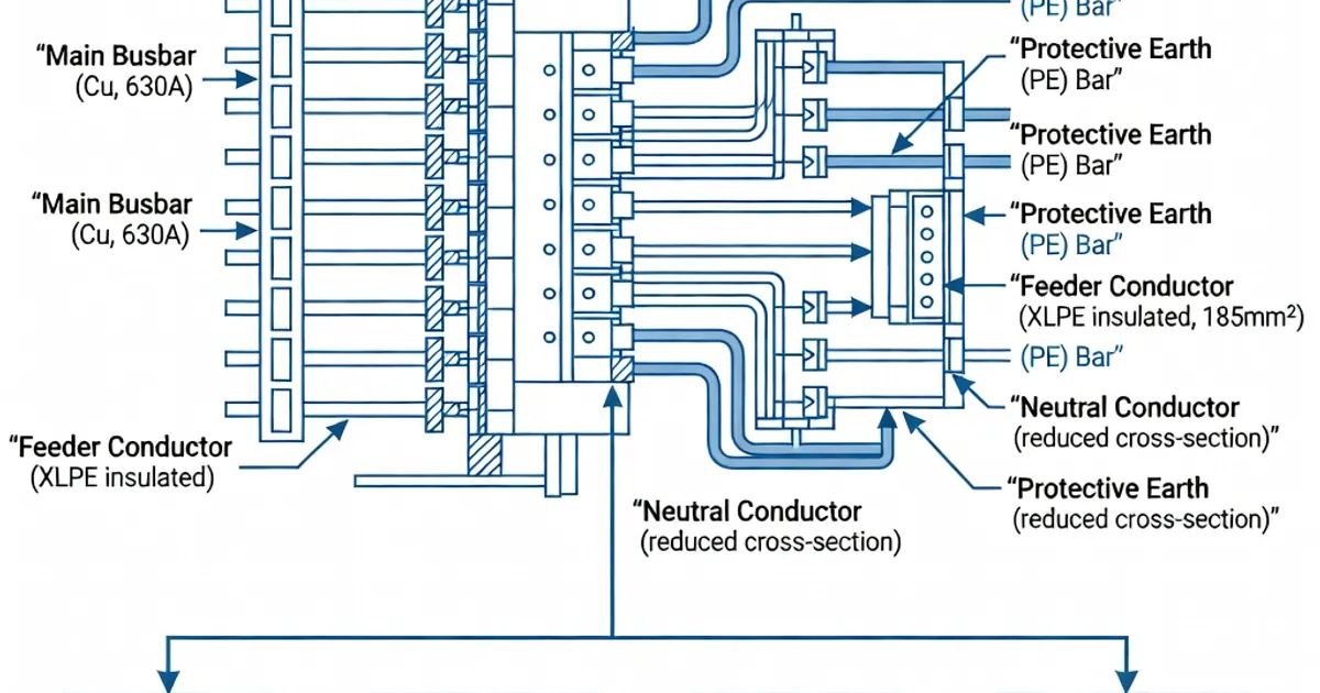
- Group sizing (125% rule): Internal conductors that carry the group of outgoing circuits must have a current-carrying capacity equivalent to at least 125% of the summed rated currents (In) of that group per IEC 61439-2 Annex H. This rule provides a thermal margin so that conductors within an enclosure will not exceed the permitted temperature rise under rated loading [IEC 61439-2; BEAMA Guide].
- Neutral conductor sizing: For copper neutrals, IEC 61439 guidance and manufacturer practice adopt 100% of the phase conductor cross-section for neutrals up to 16 mm²; for conductor cross-sections above 16 mm² the neutral may be 50% of a phase conductor cross-section with a minimum of 16 mm². Adjust proportions for aluminium conductors as required by manufacturer and national rules [IEC 61439-1; Hensel; ABB].
- Non-protected live conductors (unfused links): Live conductors that are not individually SCPD-protected (e.g., busbar tails between the main bus and the SCPD) shall be limited in length (maximum 3 m for many configurations) and must conform to the types listed in Table 4 of IEC 61439-1 (bar profiles, insulated flexible conductors, etc.). The intent is to limit stored energy and mechanical forces in the unprotected section [IEC 61439-1, Clause 8.6 & Table 4; ABB].
- Short-circuit withstand: Verify both mechanical and thermal withstand against prospective fault energy. Use the SCPD’s I²t and the conductor thermal capacity in calculations or rely upon the reference design I²t limits in Annex H if applying design-rule verification [IEC 61439-1 Clause 9.3; BEAMA].
Busbar sizing examples and rules of thumb
Manufacturers specify flat busbar cross-sections by dimension and material. Several commonly used Cu flat-bar examples and approximate assembly ratings are:
| Busbar dimension (Cu) | Typical continuous rating | Source / notes |
|---|---|---|
| 12 × 5 mm | ≈ 160 A | Siemens NXPLUS example; used for small distribution rails [Siemens / Hager] |
| 20 × 5 mm | ≈ 250 A | Common 250 A busbar in modular panels [Siemens] |
| 32 × 5 mm | ≈ 400 A | Used in heavier distribution feeders [Siemens] |
| 30 × 10 mm | ≈ 630 A | Typical 630 A busbar; selection must verify clearances and I²t [Siemens / ABB] |
These bar sizes are illustrative; final selection must verify temperature rise, voltage drop and fault I²t against the specific assembly SCPD and layout. Annex C and Annex H provide guidance for busbar spacing, support and insulation to meet the design-rule route [IEC 61439-1].
Neutral, earth and multicore considerations
Neutral (N) and protective earth (PE) conductors have special sizing provisions because of asymmetrical loading and fault currents:
- Size neutral conductors as described above (100% up to 16 mm²; 50% above 16 mm² with 16 mm² minimum), and ensure connection lugs and terminals are rated for the larger of the mechanical cross-section and the monitored current-carrying capacity [Hensel; ABB].
- Protective earth conductors must be sized to carry fault loop currents as required by national wiring rules and to survive thermal and mechanical stresses in the event of a fault; PE sizing often follows cable rules and manufacturer terminal capacity tables.
- Where multicore or insulated flexible conductors are used inside the assembly, verify their insulation rating (e.g., PVC per IEC 60227-3) and confirm the maximum permitted unprotected length of live conductors between their origin and the SCPD [IEC 60227-3; IEC 61439-1].
Short-circuit verification — thermal and mechanical checks
Short-circuit withstand requires calculations against the prospective fault current and the SCPD’s clearing characteristics:
- Compute the conductor/rail heating energy during the SCPD clearing time by integrating prospective fault current squared over time (I²t). Compare the resulting I²t with the conductor’s permissible I²t or with the design table limits if using Annex H design verification [IEC 61439-1 Clause 9.3; BEAMA].
- Check mechanical forces between conductors (electrodynamic forces) for the prospective peak short-circuit current. Ensure supports, spacers and busbar fixings can resist axial and transverse forces during the fault [IEC 61439-1].
- For assemblies adopting protective devices with known I²t characteristics (typical circuit-breaker energy let-through), use the device manufacturer’s I²t data combined with conductor thermal mass to verify survival without damage to insulation or support structures.
Voltage drop and temperature rise (continuous ratings)
Design conductors to limit voltage drop on feeders and to ensure that the conductor temperature does not exceed the limits specified for the enclosure and internal components:
- IEC 61439-1 Clause 10.9 requires that current-carrying parts be verified for temperature rise by test, calculation or by design rules; the standard assumes an average ambient of 35°C unless otherwise stated. Use cable/busbar resistance at operating temperature to calculate losses and verify that the resulting temperature rise of conductors and adjacent components remains within permitted values [IEC 61439-1 Clause 10.9].
- Voltage drop calculations follow conventional Ohmic methods; designers commonly set a design target of ≤3–5% voltage drop on final feeders depending on application and regulatory requirements. Confirm that the voltage drop does not cause overheating in conductors or devices.
Practical design workflow (step-by-step)
The following workflow aligns with IEC 61439 design-rule verification practice and industry guidance:
- Sum the rated currents (In) of the outgoing circuits that share a group feeder. Apply diversity as required by installation practice to compute group In where appropriate.
- Apply the 125% rule: size the internal group conductor or busbar so its continuous current-carrying capacity ≥ 125% × (group In) [IEC 61439-2 Annex H; BEAMA].
- Select a conductor/bar cross-section based on manufacturer ampacity tables, taking the ambient temperature (default 35°C) into account; record the selected material (Cu or Al), cross-section and insulation type.
- Verify short-circuit withstand: obtain SCPD I²t or prospective fault current and clearing time; calculate conductor thermal stress (I²t) and confirm it does not exceed conductor limits or design-table limits in Annex H [IEC 61439-1 Clause 9.3].
- Check voltage drop and temperature rise using conductor resistance at operating temperature; confirm temperature rise is acceptable per Clause 10.9 or by reference to design rules/annexes [IEC 61439-1].
- Confirm mechanical supports, clearances and creepage distances meet the recommended minimums (e.g., ≥3 mm indoor for 400 V systems where applicable) and that unprotected lengths of live conductors do not exceed 3 m for the cited arrangements [IEC 61439-1 Tables/Clauses; Hager].
- Document results, conductor tables, SCPD data and assembly drawings for the certificate of conformity and for manufacture (Clause 11 documentation requirement) [IEC 61439-1].
Manufacturer examples and industry practice
Major panel and busbar suppliers publish design data that aligns with IEC 61439 verification methods. Selected examples:
| Manufacturer | Product / Practice | Conductor / Busbar guidance |
|---|---|---|
| Siemens | NXPLUS and distribution bus systems | Cu flat bars: 12×5 mm (160 A), 20×5 mm (250 A), 32×5 mm (400 A), 30×10 mm (630 A). Flat bars verified for spacing and I²t in design guides [Siemens / Hager]. |
| ABB | Praximum / modular switchgear guides | Cu and Al conductors; terminal capacities 4–35 mm²; details in Table 4 and installation limits for non-protected conductors and connectors [ABB]. |
| Schneider / Legrand | Assembly whitepapers & guides | Document busbar and cable lug choices; demonstrate how design-rule verifications substitute for type tests in series manufacture [Legrand]. |
| Rittal / Hager / Hensel | Framework guides for enclosure layout | Provide busbar spacing, mounting ribs and module arrangements to achieve IP and thermal performance consistent with IEC 61439 [Hager; Hensel]. |
These manufacturer references are routinely used when adopting the design-rule verification route because they provide the tested reference dimensions, clearances and assembly details required by Annex H [Hager; ABB; Legrand].
Installation, mechanical and safety details
Practical workmanship details matter for compliance:
- Follow specified torque values for terminals (manufacturer’s data) to avoid overheating at connections and to ensure mechanical retention during short-circuit events [Hensel; ABB].
- Maintain specified clearances and creepage distances in the enclosure. IEC 61439 provides tables for required air gaps and creepage distances depending on rated insulation across parts and rated voltage. Reduced clearances can invalidate the Annex H design tables and require testing or calculation [IEC 61439-1].
- Locate current-carrying parts and insulating barriers to prevent unintentional contact and to limit the length of unprotected live conductors to the maxima stated by IEC and manufacturer guidance (3 m limit for many arrangements) [IEC 61439-1; ABB].
- Prefer copper conductors for compact, lower-loss installations; consider aluminium for
Related Panel Types
Frequently Asked Questions
Request a Quote
Tell us about your panel requirements and our engineering team will get back to you within 24 hours.
Email Us
[email protected]Call Us
+90 232 332 22 78