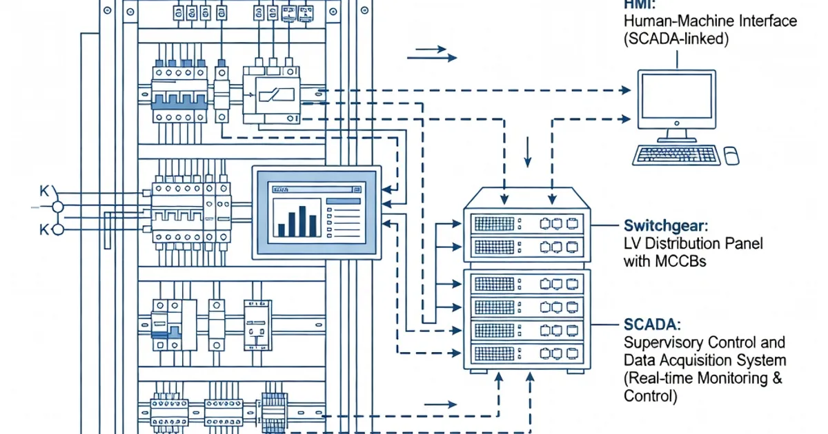
SCADA Integration in Panel Assemblies
Integrating panel assemblies with SCADA and building management systems.
SCADA Integration in Panel Assemblies
Integrating SCADA (Supervisory Control and Data Acquisition) systems into low-voltage panel assemblies requires balancing electronic control needs with electrical safety, thermal limits, and verified assembly performance per IEC 61439. This article provides a technical guide for designers and specifiers to integrate PLCs, gateways, HMIs and fieldbus/Ethernet devices into IEC 61439-compliant panels while maintaining conformity for EMC, temperature rise, short-circuit withstand, dielectric performance and accessibility.
Purpose and Scope
This guidance covers the electrical, mechanical and verification issues that impact SCADA integration in low-voltage switchgear and controlgear assemblies (LV panels). It focuses on IEC 61439-1 and IEC 61439-2 requirements (Edition 3.0, 2020), supplemented by related standards for EMC, enclosure degrees and LV switchgear practice such as IEC 61000 and IEC 60529. Where applicable, clause-level references to IEC 61439 are cited to help align design and verification activities with the standard (see References and Further Reading).
Key IEC 61439 Requirements Relevant to SCADA
| Requirement | IEC Clause / Standard | Design Value or Expectation |
|---|---|---|
| Electromagnetic compatibility (EMC) | IEC 61439-1 Clause 10.4; IEC 61000 series | Immunity to conducted/radiated disturbances; emission limits verified by testing or comparison |
| Temperature rise (ΔT) | IEC 61439-1 Clause 10.10 | ΔT ≤ 70 K at rated current (ambient ≤ 35 °C average) — ensure PLC/gateway heat accounted in thermal balance |
| Short-circuit withstand (Icw) | IEC 61439-1 Clause 10.11 | Assembly must withstand prospective short-circuit; internal wiring routes and conductor protection per clause 8.6 |
| Internal conductors and unprotected cabling | IEC 61439-1 Clause 8.6 | Unprotected flexible control cabling recommended ≤ 3 m between compartments; use terminals for larger sizes |
| Protection against electric shock / IP degree | IEC 61439-1 Clause 10.9; IEC 60529 | Basic protection IPXXB; HMIs/doors IP31–IP55 depending on environment |
| Dielectric properties (clearance/creepage and withstand) | IEC 61439-1 Clause 10.9 | Power frequency withstand and impulse withstand verified, e.g., 2 kV for 300 V rated systems |
| Routine and design verification | IEC 61439 Clause 11 (routine); design verification per Clauses 10.x | Combination of type tests, calculations and comparisons with verified assemblies |
EMC and Control Integration
SCADA devices introduce both immunity and emission concerns inside LV assemblies. Per IEC 61439-1 Clause 10.4, designers must verify that SCADA signals do not impair power distribution and that power circuits do not disrupt SCADA equipment. Follow these specific practices:
- Use shielded twisted-pair or screened Ethernet where environment or nearby switchgear will generate electromagnetic disturbances (motors, VFDs). Reference IEC 61000 series for immunity and emission test levels (IEC 61000-4 and IEC 61000-6 families).
- Segregate power and control cables using separate compartments, trays or conduits. Maintain physical separation and route SCADA wiring away from busbar runs to reduce inductive coupling.
- Implement proper cable earthing and shield termination at single point(s) to reduce circulating currents and ground loops. Verify PE continuity after assembly (recommend PE resistance < 0.1 Ω where applicable, per good practice and IEC 61439-1 Clause 10.7 verification requirements).
- Provide transient suppression (surge protection devices) at communication and power ingress points when panels interface with field networks exposed to lightning or switching surges.
These measures support verification by testing or documented comparison to a similar verified assembly, as allowed by IEC 61439 performance-based approach (Edition 3.0, 2020) [IEC 61439-1 Clause 10.4].
Thermal Management and Temperature Rise
Temperature rise control under rated current is a critical part of IEC 61439 design verification. Clause 10.10 requires the assembly to demonstrate that the temperature rise of current-carrying parts remains within limits—commonly ΔT ≤ 70 K for rated current when the ambient does not exceed 35 °C average.
- Account for SCADA equipment internal dissipation: PLCs, gateways, HMIs and power supplies add steady-state heat. Include their losses in thermal calculations or in a thermal test of the complete assembly.
- Plan ventilation or forced cooling for cabinets hosting high-density control electronics or VFDs. Ensure ventilation openings maintain required IP rating or provide filtered fans and temperature interlocks.
- Place heat-generating control devices in separate compartments (200–370 mm deep) with clearances to busbars and power devices to prevent localized hot spots. Many manufacturers recommend depth extensions (800–1000 mm) to accommodate cabling and heat management for SCADA racks.
- Use thermal simulation or IPD calculation tools for assemblies with mixed power and electronics; confirm results by type testing when required by IEC 61439 verification rules.
Short-Circuit and Internal Wiring Considerations
IEC 61439-1 Clause 10.11 requires panels to sustain prospective short-circuit conditions without creating additional hazards. SCADA wiring must therefore be routed and protected to avoid becoming a short-circuit path and to survive fault stresses:
- Keep unprotected control wiring lengths ≤ 3 m where practical as recommended by Clause 8.6 to limit their exposure to fault current. For longer runs, use protected conductors or enclose in metallic conduits to maintain assembly integrity.
- Use terminal blocks and barrier-type connectors for interface points; avoid direct soldered or loose connections for sizes > 16 mm²—terminalisation ensures predictable thermal and fault behavior.
- Design cable harnesses with segregated power, control and measurement conductors, and use adequate insulation systems compliant with expected thermal and voltage stress levels.
IP Degrees, Enclosures and Accessibility
Panel enclosures and HMI areas must provide both electrical safety and appropriate environmental protection. IEC 61439-1 Clause 10.9 and IEC 60529 specify protection degrees:
- Basic accessibility protection inside panels follows IPXXB for finger access, but front-access HMIs and operator doors commonly require IP31 up to IP55 depending on the site environment (e.g., IP55 for dusty/washdown locations) [IEC 60529].
- Design door seals and HMI mountings so that gaskets do not compromise ventilation needed for thermal control. Where cooling is required, use filtered vents or IP-rated fan modules.
- Provision clear, secure operator access to HMIs while ensuring live parts remain appropriately guarded per Clause 10.9 and IEC 60439 legacy principles.
Dielectric Performance and Clearances
Dielectric withstand and appropriate clearances/creepage distances ensure SCADA electronics and their interfaces tolerate transient voltages and do not create flashover risks. IEC 61439-1 Clause 10.9 requires dielectric verification consistent with the rated voltage of the assembly.
- Verify power-frequency withstand (for example, 2 kV power-frequency test for a 300 V rated system) and impulse voltage withstands per the rated insulation coordination of the assembly.
- Maintain sufficient clearances between power conductors and control electronics; insulate or shield control modules mounted adjacent to busbars or power terminations.
Functional Operation and Routine Verification
IEC 61439 mandates both design verification and routine verification. Clause 11 includes mechanical and operational checks that impact SCADA integration:
- Verify mechanical operation of doors, interlocks and HMIs during routine checks. HMI accessibility and operation under door-open/closed states must not compromise protective measures.
- Perform EMC and functional tests on representative assemblies or full panels where control logic and communications are integral to operation—this may include simulated field signals to validate SCADA I/O and gateway behavior under electrical stress.
- Document manufacturer or assembler comparisons to verified assemblies if using the comparison route allowed by IEC 61439 rather than full type tests. Maintain records of calculations and component qualifications used in the comparison approach.
Design Best Practices for SCADA-Ready IEC 61439 Panels
Industry experience and manufacturer guidance converge on practical measures that simplify verification and increase operational reliability:
- Modular functional units: Architect the panel around discrete functional units (power distribution, motor control, SCADA rack) to simplify thermal and short-circuit verification and to isolate noise sources. Use DIN-rail mounted PLCs and gateways in dedicated compartments.
- Compartmentalization: Segregate power busbars, LV switchgear and sensitive electronics into separate compartments with metallic partitions and cable glands to meet Clause 8.6 recommendations for internal conductors.
- Shielding and cable management: Use screened communications and maintain firm shielding termination practices. Keep Ethernet cables away from main busbar corridors and high-current conductors.
- Use of pre-tested modules: Where possible, employ pre-certified or factory-tested combinations (e.g., certified PLC/busbar modules) to enable comparison verification per IEC 61439 and reduce on-site testing scope. Major vendors provide verified combos—see Product Examples table below.
- Thermal margin and redundancy: Size ventilation and power supplies to maintain thermal margins and allow for future modules. Design for a common ambient of ≤ 35 °C per IEC 61439-1 thermal limits.
- Earthing and equipotential bonding: Provide dedicated PE runs to SCADA racks and HMIs; test PE continuity and bonding resistance during routine verification.
- Allow service space: Provide depth and cable bend space (recommend 800–1000 mm cabinet depths for complex SCADA racks) to facilitate cable routing without compromising heat dissipation.
Manufacturer Examples and Selection Criteria
Major switchgear and panel manufacturers offer IEC 61439-compliant assemblies with native SCADA integration capabilities. Evaluate vendor offerings by protocol support, mechanical footprint, short-circuit ratings, IP degree options and verification documentation.
| Brand / Product | Key SCADA Features | Typical Ratings (A / Icw) | IP / Notes |
|---|---|---|---|
| Siemens - NXPLUS C / SENTRON PowerCenter | TIA Portal integration; Profinet / Ethernet; modular PLCs and diagnostics | Up to 4,000 A; Icw 50–100 kA (application dependent) | IP43–IP55; verified assemblies & documentation available [7] |
| ABB - UniGear / System pro E | Modbus TCP / Profibus; integrated HMIs; factory-tested combos | 25–2,500 A | IP31–IP54; IEC 61439-2 verified practice guide available [3] |
| Schneider Electric - Okken / BlokSeT | EcoStruxure SCADA integration; Ethernet/IP; pre-tested assemblies | 36–150 kA Icw range in assemblies | IP30–IP54; manufacturer guidance on verification and combos [4] |
| Eaton - Power Xpert UX | Modbus / DNP3 support; integrated monitoring; scalable racks | Up to 6,300 A in some systems | IP30–IP43; RDF-optimised configurations [5] |
| Rittal / Ri4Power | Modular cabinets for PLCs and Ri4Power software integration; thermal imaging validated | 400–5,000 A typical ranges | IP55 options; modularity supports SCADA compartment design [8] |
When selecting a supplier, request the IEC 61439 verification dossier, thermal calculation reports, EMC compliance statements and example wiring diagrams showing SCADA integration. These documents accelerate the comparison or calculation route allowed by IEC 61439 design verification.
Verification Strategy: Tests, Calculations and Comparison
IEC 61439 emphasizes performance verification rather than prescriptive type testing. For SCADA-integrated panels employ a hybrid verification strategy:
- Design calculations: Thermal calculations including SCADA heat dissipation, voltage drop and short-circuit calculations for cable routing and terminal sizing.
- Type or sample testing: Where assemblies include novel layouts or high-density electronics, perform sample thermal and EMC testing to validate assumptions—this is essential when extrapolating to larger panels.
- Comparison method: Use manufacturer-supplied verified assembly reports and comparison with similar assemblies when appropriate per IEC 61439-1 guidance. Maintain strict documentation showing equivalence in configuration, current ratings and construction.
- Routine verification: Conduct mechanical operation checks, insulation resistance checks, continuity and PE bonding tests, and functional tests of SCADA devices after integration into the final assembly (Clause 11).
Practical Implementation Checklist
- Define the required SCADA protocols and physical interfaces early (Modbus TCP, Profinet, DNP3, Ethernet/IP) to ensure correct gateway selection and separation of networks.
- Allocate a dedicated SCADA compartment with DIN-rail space (10–36 module PLCs), filtered
Related Panel Types
Frequently Asked Questions
Request a Quote
Tell us about your panel requirements and our engineering team will get back to you within 24 hours.
Email Us
[email protected]Call Us
+90 232 332 22 78