Forms of Internal Separation (Form 1–4b)
Complete guide to forms of internal separation in IEC 61439 panel assemblies.
Forms of Internal Separation (Form 1–4b)
This article explains the Forms of Internal Separation defined by IEC 61439 for low-voltage switchgear and controlgear assemblies (ASSEMBLIES). It describes the progressive levels of segregation between busbars, functional units (FUs) and terminals from Form 1 (no segregation) through Form 4b (maximum segregation), summarizes the required verification tests and applicable clauses of the standard, and provides practical guidance and manufacturer examples for selecting an appropriate form for a project. Per IEC 61439-2 Clause 8.4 and Table 104, the selection of a form defines the protective barriers and construction required to limit access to live parts and to reduce the risk of direct and indirect contact (see References and Further Reading).
Overview
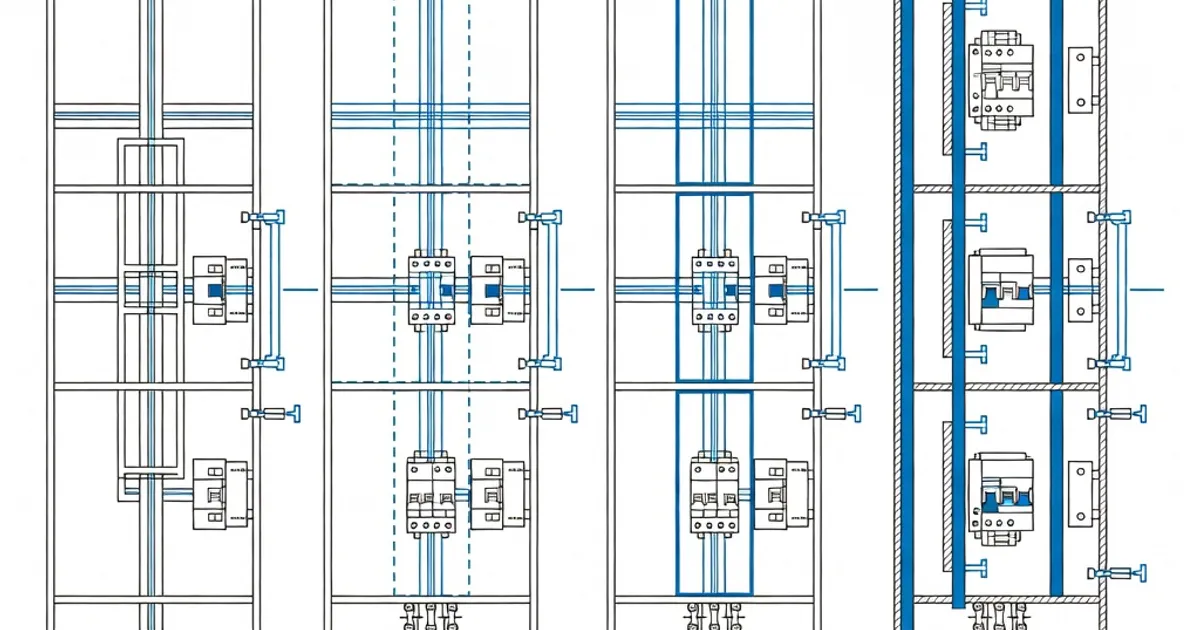
Forms of internal separation specify how assemblies subdivide the interior into compartments using metallic partitions, insulating barriers, shrouds and dedicated terminal compartments. The goal is to protect personnel, improve maintainability and control the fault and arc propagation paths inside the enclosure. The forms are defined in IEC 61439-2 (power switchgear and controlgear assemblies) while IEC 61439-1 provides general verification and performance requirements that apply to all forms (e.g., temperature rise, dielectric strength, IP/IK ratings) (see IEC 61439-1 and IEC 61439-2 in References).
Protection against direct contact is generally associated with achieving at least IP2X (finger-safe) access to live parts as referenced to IEC 60529; the standard also requires that internal barriers maintain mechanical strength, thermal stability and not compromise declared enclosure IP/IK ratings during normal use and under fault conditions (see IEC 60529 and IEC 61439 Clauses cited below).
Why the Form Matters
- Safety: Higher form numbers reduce the probability of accidental contact with live parts and confine faults to limited compartments.
- Maintainability: Segregated FUs allow safer live-front maintenance and replacement of modules without exposing adjacent circuits.
- Fault performance: Segregation helps manage the effects of short-circuits and internal arcs, improving predictability of fault currents and thermal loading.
- Regulatory and client requirements: Critical facilities (data centres, hospitals) frequently mandate Form 3b or Form 4b to limit exposure and downtime.
Detailed Description of Forms (Form 1 through Form 4b)
The table below summarizes each Form, the typical construction requirements and the common sub-variants described in IEC 61439-2 Table 104 and in industry practice.
| Form | Main Separation Requirements | Common Sub-variants / Notes |
|---|---|---|
| Form 1 | No segregation between busbars, FUs and terminals. Live parts may be accessible only behind the enclosure front; individual FUs are not partitioned. | Lowest protection level. Acceptable for fully restricted areas or simple installations where live-front maintenance is not performed. (IEC 61439-2 Table 104) |
| Form 2 | Busbars are separated from the functional units. FUs are not separated from each other. Terminals may share the FU compartment. Separation often achieved via insulating busbar covering or partition. | 2a: Busbar insulated only; 2b: Busbar fully partitioned from FUs. Common choice where busbar access must be prevented but FU-to-FU segregation is not required. |
| Form 3 | Busbars separated from FUs and FUs separated from each other (FU-to-FU partitions present). Terminal separation may be optional depending on sub-variant. | 3a: Terminals may be in the FU space; 3b: Terminals are separated from FUs (additional terminal compartment or IP2X shrouding). Prioritised for installations requiring live-front FU replacement without exposing adjacents. |
| Form 4 | As Form 3 but with terminals for external conductors separated from the FUs. Terminals are in dedicated compartments that isolate external connections from live FU internals. | 4a: Terminals separated in a shared terminal compartment; 4b: Terminals in individual or fully partitioned terminal compartments per circuit — maximum segregation. Often specified where cable management and external conductor segregation are critical (IEC 61439-2 Clause 8.4.2.2). |
Different national implementations and manufacturer product families expand these forms into Types (e.g., the UK/BS EN National Annex defines Types 1–7 as additional subdivisions of Form 4b in practice). These Types address details such as common glanding, individual circuit glanding and fully partitioned busbar/terminal routing (see BS EN guidance and manufacturer application notes).
Form 4b — The Highest Level of Internal Segregation
Form 4b provides the most rigorous internal separation. It places each terminal (particularly the connections for external circuits) in its own compartment or otherwise fully isolates terminals from FUs and busbars. Form 4b is commonly specified where maintenance on installed cabling or selective circuit replacement must occur without exposing personnel to adjacent live parts. Because Form 4b minimizes the length of unprotected conductors inside the enclosure and often requires busbar covers, it also reduces touch and arc propagation risk. Many manufacturers offer Type extensions for Form 4b to address cable entry and glanding strategies (see manufacturer technical papers).
Verification and Tests Required by IEC 61439
IEC 61439 establishes mandatory verification tests and routine checks to confirm that the chosen form of separation meets the intended performance. Key verifications include:
- Temperature Rise (Clause 10.2 IEC 61439-1): Assemblies must be demonstrated to limit temperature rise within the specified limits; typical design verification requirements ensure conductor and enclosure temperature does not exceed the declared ratings under rated currents (often evaluated at reference ambient temperatures such as 35 °C). The standard sets objective criteria the manufacturer must verify before issuing a declaration of conformity.
- Dielectric Testing (Clause 10.9 IEC 61439-1): Dielectric tests confirm the integrity of insulation and barriers and are part of the design verification. The assembly shall withstand the required test voltages and impulse requirements where applicable.
- Mechanical and Thermal Stability (Clause 10.10): Components such as live-part supports and insulating barriers must demonstrate mechanical strength and thermal stability. The ball pressure test at 125 °C is commonly referenced for insulating supports and supports that may be subject to elevated temperatures during operation.
- Short-Circuit and Electrodynamic Withstand (Clause 10.11): Assemblies must withstand prospective short-circuit forces and thermal energy. The separation form impacts prospective conductor routing and the assembly’s short-circuit behaviour; therefore short-time withstand and stability are verified as part of assembly type testing.
- Ingress Protection (IEC 60529): Internal barriers must not compromise the declared IP rating. For live-part protection the assembly should generally provide IP2X access protection to live parts reachable from the front or during reasonable maintenance operations.
Verification is normally performed by the manufacturer as declared in technical documentation and supported by type tests or combinations of type and routine tests. Users must be cautious about altering internal wiring or modifying barriers after delivery because changes may invalidate the original verification (IEC 61439-1 requires re-assessment for modifications that affect compliance).
Common Quantitative Limits and Practical Rules
- Designers typically limit the length of exposed or unprotected conductors inside compartments to short distances to reduce shock risk and arc propagation (industry practice often limits unprotected conductor lengths to around 3 m inside enclosures where IP2X cannot be maintained) (see ABB application guidance).
- Insulating covers and barriers must withstand the declared thermal and mechanical loads, usually validated by temperature-rise and ball-pressure testing at 125 °C for live-part supports (IEC 61439-1 Clause 10.10).
- IP2X (finger-safe) is the accepted minimum for internal live-part protection in accessible areas; where operatives may reach into compartments, shrouded terminals or separate terminal compartments are required to achieve the required degree of protection (IEC 60529, IEC 61439).
Design Best Practices and Industry Experience
Experience from major manufacturers and system integrators shows the following pragmatic recommendations:
- Use Form 3b or 4b in public or partially accessible installations: These forms permit safe front access and maintenance with reduced risk of accidental contact. Hospitals, data centres and commercial buildings commonly specify Form 4b for critical distribution boards (see manufacturer catalogs).
- Clarify terminal arrangements early in the project: Whether individual circuit glanding, common gland plates or busbar trunking will be used affects which Form/Type is practical and the necessary cable-entry compartmentation (BS EN extensions describe Types 5–7 for cable termination strategies).
- Respect verification envelope: Avoid post-delivery modifications (adding cables, moving FUs) that alter separation distances or bypass barriers; any such change may require re-verification or retrofit solutions.
- Coordinate arc-flash mitigation with form selection: Although forms are primarily about personnel contact protection, partitioning also limits arc propagation and can complement other arc-mitigation measures such as selective protection, arc detection and ventilation.
- Consider thermal management: Additional partitions and terminal compartments may reduce natural convection cooling for some FUs; ensure temperature-rise verification takes the final arrangement into account (IEC 61439-1 Clause 10.2).
These recommendations align with manufacturer application notes and guidance published by ABB, Siemens and others (see References for specific manufacturer technical papers).
Manufacturer Examples and Typical Product Options
Most major switchgear manufacturers offer configurable panel systems that can be supplied in Forms 1–4b, often with Type extensions for terminal compartmenting. Typical product features include shrouded and insulated busbars, removable partitions, dedicated terminal compartments with gland plates and IP-compliant covers, and modular FUs that fit into partitioned bays for safer maintenance.
| Manufacturer | Product Line / Features | Forms / Types Typically Offered |
|---|---|---|
| Siemens | NXPLUS / NXLIGHT families with shrouded terminals, modular FUs and IP42–IP65 options; modularity facilitates Form 3b/4b configurations. | Form 1–4b; Type options via configurator (see Siemens literature and product catalogs). |
| ABB | UniGear / UniSwitch — offers busbar insulation, partitioned compartments and detailed guidance on separation and conductor routing in technical application papers. | Form 1–4b. Application papers show how to achieve Form 3b and Form 4b for site-critical installations (see ABB application documents). |
| Schneider Electric | Blokset / Okken and other low-voltage distribution systems with partitioned cubicles and terminal compartments; arc-resistant options available. | Form 1–4b, with product options tailored to cable entry and glanding needs. |
| Eaton | Power Xpert and Distribution switchgear offering modular FUs, optional fully partitioned terminal compartments and arc mitigation features. | Form 2b–4b typical across product families; arc-resistant and ruggedized options often provided. |
Consult the manufacturer's technical application papers and type-test reports to confirm the declared form and any Type-level extensions. Manufacturers publish guidance on how to achieve specific forms and the limits of permissible wiring and conductor routing without invalidating the declared configuration (e.g., ABB Technical Application Paper No. 11 and ABB workbook on IEC 61439 practice).
Practical Application Examples
- Small commercial distribution board: Form 2b is often sufficient — busbars insulated and separated from FUs but FUs not individually partitioned. This balances cost and improved busbar safety for routine installations.
- Building main distribution for office tower: Form 3b is a common choice, providing FU-to-FU separation and separated terminals so routine maintenance on one FU does not expose neighbouring equipment.
- Critical facility (data centre, hospital): Form 4b with Type-level terminal segregation is typically preferred to allow safe, live-front changes and minimize downtime and risk. Form 4b is particularly useful where individual circuits need to be disconnected or re-terminated without opening adjacent compartments.
Common Mistakes and Pitfalls
- Specifying a form but failing to require documented verification and type-test evidence from the manufacturer. IEC 61439 requires appropriate verification; ask for the relevant type test reports and declarations.
- Post-delivery modifications to internal wiring or adding cable glands that compromise partitions or IP protection — such changes can invalidate the original verification and the declared form.
- Ignoring thermal impacts of partitions and terminal enclosures: additional segregation can change airflow and temperature rise characteristics and therefore the assembly’s rated current capability unless verified.
- Assuming that “shrouded” equals full segregation — verify whether the shrouding achieves the required IP2X protection and mechanical/thermal ratings as called out in IEC 61439.
Summary
Forms of internal separation per IEC 61439 describe progressively stricter compartmentation, from Form 1 (no
Related Panel Types
Frequently Asked Questions
Request a Quote
Tell us about your panel requirements and our engineering team will get back to you within 24 hours.
Email Us
[email protected]Call Us
+90 232 332 22 78