EMC Requirements for Panel Assemblies
Electromagnetic compatibility requirements and best practices for IEC 61439 panels.
EMC Requirements for Panel Assemblies
This article explains electromagnetic compatibility (EMC) requirements for low-voltage panel assemblies designed and verified to IEC 61439. It summarizes the standard requirements, related standards and tests, pragmatic design and verification practices for panel builders, and examples of how major manufacturers address EMC in compliant assemblies. The guidance here references IEC 61439-1:2020 Clause 10.2.2 and related authoritative sources to help panel designers and builders integrate EMC controls into compliant low-voltage switchgear and controlgear assemblies (LV-SCAs).
Overview: Why EMC matters in IEC 61439 assemblies
Electromagnetic compatibility is essential to ensure that an assembly neither emits excessive electromagnetic disturbances nor suffers unacceptable performance degradation from external electromagnetic phenomena. Per IEC 61439-1 Clause 10.2.2, panel assemblies must be constructed and verified with EMC in mind so that embedded electronic devices (e.g., electronic trip units, PLCs, power meters) perform reliably within their intended environment (industrial, commercial or residential) without causing unacceptable emissions to neighboring equipment (see IEC 61439-1:2020 Clause 10.2.2) [5][7].
Key practical reasons to treat EMC as a design requirement:
- Electronic control and protection devices have increasing sensitivity to conducted and radiated disturbances (harmonics, transients, ESD, EFT, conducted surges).
- Large current-carrying conductors and switching events inside metal-clad assemblies generate emissions that can couple to control circuits and to external equipment.
- Regulatory and contractual compliance requires documented design verification and retention of evidence in the manufacturer’s technical file for the Declaration of Conformity.
Scope and applicability
IEC 61439 applies to LV panel assemblies up to 1000 V AC and 1500 V DC; performance-specific rules for power switchgear and controlgear assemblies are given in IEC 61439-2 (PSCs) [3][6]. EMC design verification in IEC 61439-1 applies across the standard and specifically requires verification that the assembly limits emissions and has adequate immunity in its intended environment (industrial, commercial, residential) using tests from generic or product EMC standards [5][7].
Relevant standards and how they interact
EMC verification for a panel assembly is not performed by a unique IEC 61439 EMC test. Instead, IEC 61439 mandates that assemblies be verified using the applicable product family standard (for example IEC 60947 series for switchgear) or the generic IEC 61000 series for emission and immunity requirements. The table below summarizes the principal standards and their EMC relevance.
| Standard | Focus | EMC relevance (typical clauses) |
|---|---|---|
| IEC 61439-1:2020 | General rules for LV assemblies | Clause 10.2.2: design verification for emissions and immunity; links to product/generic EMC tests [5][7] |
| IEC 61439-2:2020 | Power switchgear and controlgear assemblies (PSCs) | Applies IEC 61439-1 EMC rules to PSC assemblies; additional performance criteria for high-power equipment (>25 kW typical scope) [3][6] |
| IEC 60947 series | Low-voltage switchgear and controlgear product standards | Product-level EMC tests (e.g., circuit-breaker immunity/emission characteristics) used to support assembly verification [5] |
| IEC 61000 series | Generic EMC immunity and emission tests | Defines environment-based immunity/emission limits (industrial, residential) and test methods to apply when product standards are insufficient [5] |
| IEC 60529 | Degrees of protection (IP codes) | Enclosure ingress protection affects shielding and therefore EMC; IP ratings influence enclosure selection and gland/cable sealing strategy [2] |
| IEC 62271 series | High-voltage switchgear | Occasionally cross-referenced for hybrid installations but not primary for LV EMC requirements [6] |
IEC 61439 replaces the older type-test-focused IEC 60439 approach with a performance-based design verification model. That shift places responsibility on the assembly manufacturer to demonstrate, by calculation, similarity to tested reference designs or by test, that the final assembly meets EMC objectives [1][5].
Design requirements and verification approach in IEC 61439
IEC 61439 requires the panel builder to verify construction to limit electromagnetic emissions and ensure adequate immunity. The standard allows three principal verification routes:
- Use the results of applicable product-family EMC tests (for components tested to IEC 60947 product standards) as evidence that the assembled product will meet EMC objectives [5].
- Use generic EMC tests from the IEC 61000 series to directly verify emissions and immunity for the complete assembly where product tests are insufficient or when the assembly introduces new risk factors (e.g., long unshielded harnesses, in-panel radio equipment) [5].
- Apply design rules and calculation methods and, where appropriate, rely on similarity to a previously tested reference design (reference design verification). IEC 61439 permits verification by similarity when the assembly’s bounding parameters (current ratings, enclosure type, cable routing, shielding) remain within the reference design limits [5].
Important clause references and practical thresholds:
- IEC 61439-1 Clause 10.2.2 specifies that EMC shall be verified by relevant product or generic EMC tests and that the panel builder shall keep evidence in the technical documentation [5][7].
- Assemblies rated up to 1000 V AC / 1500 V DC are covered by IEC 61439; for PSCs IEC 61439-2 gives application-specific expectations, including for assemblies above typical distribution levels [3][6].
- Industry practice often uses reference-assembly testing to avoid full re-testing; however modifications beyond the tested envelope (for example increasing short-circuit current rating significantly, adding unshielded instrumentation cabling, or changing enclosure type) typically require additional EMC verification or testing [5].
Practical design measures to control emissions and improve immunity
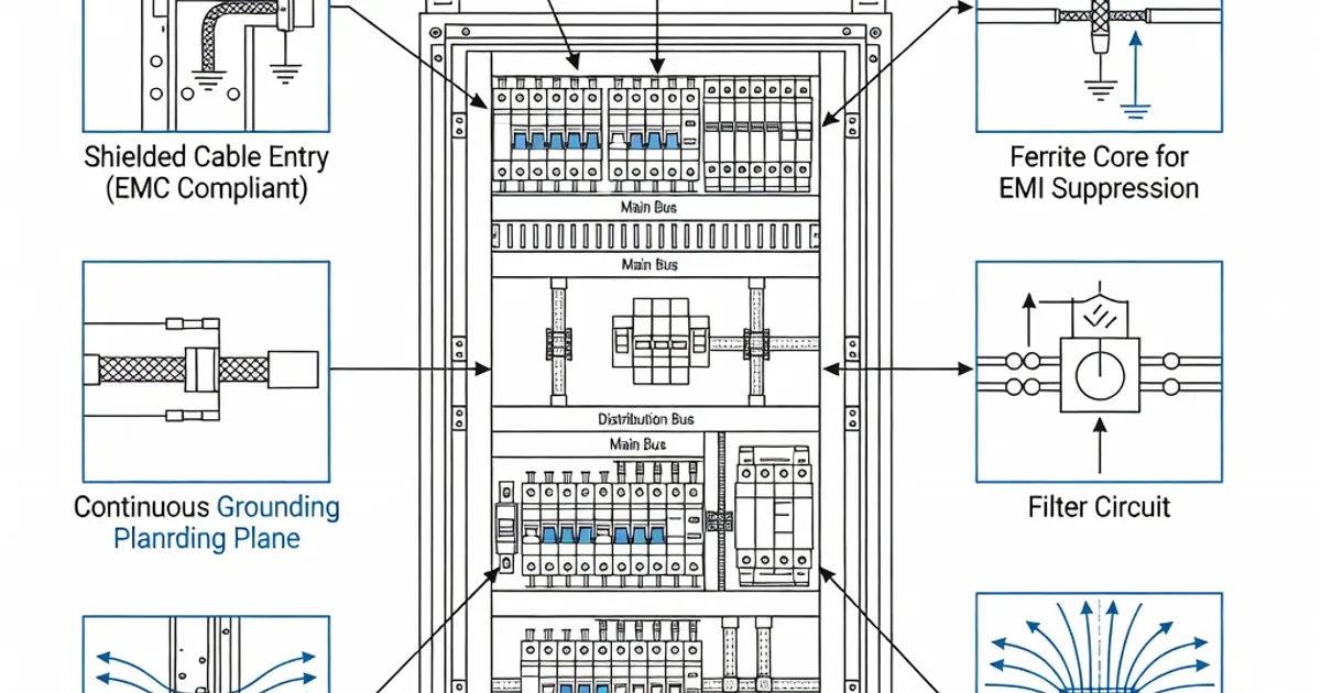
Panel builders reduce EMC risk by combining component selection, mechanical enclosure design, cable management, grounding/bonding strategy, and filtering. The following practical measures reflect industry best practice and guidance from leading manufacturers and IEC guidance documents [2][3][4][5][6]:
- Use certified components: Select circuit-breakers, contactors, electronic trip units, meters and PLCs that are tested to the applicable IEC 60947 or IEC 61000 product standards. Components with documented EMC characteristics simplify assembly verification [5][6].
- Enclosure shielding and IP selection: Use continuous metal enclosures with conductive gaskets, grounded doors and gland plates. An enclosure with an appropriate IP rating (IP31 through IP55 depending on the environment) improves both ingress protection and electromagnetic screening effectiveness (see IEC 60529) [2].
- Grounding and bonding: Provide low impedance equipotential bonding between doors, panels, gland plates and cable screens. Ensure protective earth connections are sized per conductor selection and routed to minimize loop areas for high-frequency currents. Effective bonding reduces radiated emissions and improves immunity.
- Cable segregation and routing: Separate power conductors from control and signal wiring. Keep control cable lengths short where possible, route signal cables orthogonally to large power runs, and use dedicated cable ducts or screened compartments to limit coupling [3][4].
- Use of filters and suppression components: Fit EMI filters, surge suppressors (e.g., SPD), and common-mode chokes at panel inputs and for sensitive subsystems as needed. Ferrite beads and snap-on ferrites on signal and data cables reduce high-frequency emissions and improve immunity.
- Arc management: Design to limit arcing and its radiated emissions by using arc-proof compartments or arc-guiding channels for switchgear with high fault energies; minimize unconfined arcing that can produce transient emissions [1].
- Thermal-EMC interactions: Recognize that EMC measures can influence thermal performance (e.g., filters add losses). IEC 61439 requires verification of temperature rise (Clause 10.2) separately; coordinate thermal and EMC design so one does not invalidate the other [1][5].
Verification strategies: calculation, reference designs, and testing
IEC 61439 allows validation by calculation, similarity to a tested reference design, and testing. The choice depends on the assembly’s risk profile and degree of deviation from known designs.
- Reference design approach: Many panel builders leverage tested reference assemblies and supplier technical guidance to cover 80–90% of typical builds without full re-testing. For example, system providers such as ABB and Hager publish design guides and checklists to help panel builders demonstrate similarity and retain evidence for the technical file [2][6]. Use this approach when the assembly’s enclosure, conductor routing, current rating and components stay within the reference limits; if modifications exceed the envelope (for example increase of rated current to >1600 A or change of enclosure shielding) plan additional verification [5].
- Component-based verification: When all major components are certified to relevant product EMC standards (IEC 60947 and IEC 61000 product parts), document how their installed configuration preserves the tested conditions. Demonstrate that installation details (e.g., cable lengths, screening, bonding) do not introduce new coupling paths.
- Assembly-level EMC testing: Where calculations or similarity are insufficient, perform relevant IEC 61000 generic tests (radiated emission, conducted emission, EFT, surge, ESD, conducted/radiated immunity) on the complete assembly in the environment for which the assembly is intended. IEC 61439 does not mandate routine factory EMC tests; it requires design verification using one or more methods described above [5].
Common pitfalls and industry experience
Panel builders commonly encounter the following compliance pitfalls, as reported by manufacturers and technical guides:
- Unvalidated modifications: After initial verification, field modifications (adding meters, longer cables, or aftermarket devices) can invalidate EMC verification if they introduce new emission sources or coupling paths. Keep change-control and re-verify where necessary [2][4].
- Overlooking ambient and installation context: Designs verified at 25–35 °C may fail when installed in higher ambient temperatures; similarly, proximity to other equipment or conducting surfaces can alter immunity/emission performance. IEC 61439 requires the intended operating environment to be considered within the verification process [1][3].
- Insufficient documentation: Manufacturers must retain evidence — datasheets, test reports, design calculations and checklists — that demonstrate compliance for the Declaration of Conformity. Panel builders who cannot produce this technical file risk non-compliance [2][4].
- Assuming product-level EMC equals assembly compliance: Components may be EMC-compliant individually but, when combined, coupling and cable routing can create new emission/immunity issues. Verify integration as part of the assembly evidence package [5].
Manufacturer practices and product examples
Major suppliers of LV switchgear provide tested reference assemblies, application guides and product-level EMC documentation that panel builders commonly use to support verification. Examples include:
- Siemens: SIVACON and Sentron product families include technical design guidance and shielded enclosure options; Siemens documents use of IEC 60947 components and reference arrangements to support panel EMC verification in industrial environments [source: vendor documentation].
- ABB: ABB’s UniGear and related systems provide Technical Application Papers that explain how to apply IEC 61439-1/2 verification principles, including EMC considerations and use of product-standard test results to establish assembly compliance [6].
- Schneider Electric: Schneider’s guidance describes the shift to design verification under IEC 61439 and practical steps for achieving EMC compliance using EcoStruxure and other components tested to IEC 61000 series product standards [3].
- Eaton, Rittal, Hager, Hensel and Legrand: Each provides enclosure systems, documentation, and checklists that panel builders use to demonstrate EMC control through shielding, bonding and component selection [2][4][8].
These vendors typically encourage panel builders to use their validated system documentation and reference assemblies to cover common configurations and accelerate conformity assessment while acknowledging that deviations require additional verification [2][3][6].
EMC design checklist for IEC 61439 assemblies
Use the following checklist during design and verification to build the technical documentation required by IEC 61439:
- Identify intended environment (industrial/commercial/residential) and apply appropriate IEC 61000 immunity/emission levels.
- Select components with IEC 60947/IEC 61000 product-level EMC certificates and keep datasheets in the technical file.
- Define enclosure type and IP rating; document bonding/earthing arrangements and conductive gasket use.
- Document cable routing, segregation, and screen termination practices; show maximum cable lengths used relative to reference designs.
- Specify EMI filters, surge protection devices and ferrites where used, including insertion loss or attenuation specifications.
- Record reference design/test reports; where changes occur, conduct additional calculations or testing as required.
- Include temperature rise verification and explain thermal-EMC trade-offs (filter heat losses, ventilation impacts).
- Maintain a change-control process and re-verify EMC after significant modifications.
Comparison: Typical EMC controls and when to test
Related Panel Types
Frequently Asked Questions
Request a Quote
Tell us about your panel requirements and our engineering team will get back to you within 24 hours.
Email Us
[email protected]Call Us
+90 232 332 22 78