Busbar Sizing Calculations for Panel Assemblies
How to size copper and aluminium busbars for IEC 61439 panel assemblies.
Busbar Sizing Calculations for Panel Assemblies
This technical guide explains how to size busbars for IEC 61439 low-voltage switchgear and controlgear assemblies (LVSGA). It covers the principal verification checks required by the standard—current-carrying capacity, temperature rise and short-circuit withstand strength—provides calculation procedures, gives worked examples and presents manufacturer practice and typical busbar specifications. Where relevant, the text cites specific IEC 61439 clauses and manufacturer data to support design decisions.
Scope and applicability
This article applies to busbars used inside panelboards, switchgear assemblies and busbar trunking systems intended to meet IEC 61439-series requirements. It addresses copper and aluminium busbars in ventilated and enclosed assemblies, and includes the practical derates and verification steps commonly used in industrial and commercial LV installations. Use this guidance alongside formal verification tools from busbar manufacturers and the normative text of IEC 61439-1 and IEC 61439-6 when preparing a final design and test plan.
Standards and normative references
Design and verification must reference the applicable parts of the IEC 61439 family and supporting standards:
- IEC 61439-1 — General rules, including temperature-rise verification and limits (see Clause 10.10 and Table 6) for busbars and connections [IEC 61439-1]. Per IEC 61439-1, check temperature rise under rated current and verify maximum allowable temperature differences for busbar connections and terminals [1][8].
- IEC 61439-6 — Rules specific to busbar trunking systems, including definitions, construction, and short-circuit withstand criteria for trunking up to specified ICW values [7][9].
- IEC 60947 series — Requirements for associated low-voltage switchgear, torque and terminal practices (e.g., recommended terminal torques) [2].
- IEC 60364 — Voltage drop calculation methods used to ensure supply voltage quality and limit voltage drop to 3–5% as part of a panel design [5].
- IEC 60529 — Enclosure ingress protection (IP) ratings that influence thermal dissipation and therefore derating factors for busbar current capacity [1].
When designing, also consult manufacturer technical guides and verified calculators (e.g., Hensel, Wöhner, Siemens, ABB) for certified data and short-circuit capability tables [2][3][6].
Key parameters and limits
1. Operating current (Ib) and design current
Compute the design load current for three-phase loads using:
I = P / (√3 × V × cos φ)
Where P is active power (W), V is line-line voltage (typically 400–415 V for LV systems) and cos φ is the power factor. IEC 61439 practice commonly applies a 125% factor to continuous load current when selecting busbar cross-sections (i.e., design for 1.25 × Ib) to cover overload and long-term duty considerations [1][4].
2. Cross-section sizing (A = I / k)
Once the design current is known, determine required conductor cross-sectional area A (mm²) from a current-density factor k, which depends on material, operating temperature class and installation conditions:
- Copper k typical range: approximately 1.0–1.2 A/mm² for busbars operating up to 105°C in ventilated assemblies; for conservative designs use 1.0 A/mm² unless manufacturer data indicates otherwise [1][4].
- Aluminium k typical range: approximately 0.6–0.8 A/mm² for equivalent temperature class because aluminium has higher resistivity and lower heat capacity than copper [1].
Thus, cross-section A = I_designed / k. After calculation, select the nearest standard busbar size (examples in the table below).
3. Temperature rise limits
IEC 61439-1 Table 6 provides temperature-rise limits for busbar connections and terminals. Typical limits frequently applied in practice include:
- 70 K temperature rise limit for busbar connections (commonly used for bare copper busbars in ventilated panels); this equates to a maximum busbar temperature of 70 K above ambient for the considered test condition, subject to the specific table and conditions [8].
- Alternative limits: 75 K for silvered connections and 85 K for certain terminal categories as specified by the standard [8].
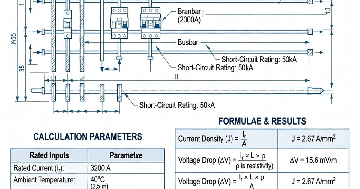
Practical example data: a 20 × 10 mm copper busbar may carry about 652 A at 35 °C ambient and 85 °C busbar temperature, but derates to ~508 A at 55 °C ambient—illustrating the sensitivity of current capacity to ambient temperature and permitted busbar temperature [6].
4. Short-circuit withstand (ICW and Icw)
Short-circuit mechanical and thermal withstand capability depends on cross-sectional area, bar thickness, number and spacing of supports, and connection details. For busbar trunking, IEC 61439-6 sets typical short-circuit withstand categories and calculation methods [7]. Example values from published tools and manufacturer data:
- 20 × 10 mm copper busbar with support spacing of 300 mm (two supports per span) can achieve around 53 kA peak short-circuit withstand (1 s thermal equivalent), dropping to approximately 43 kA at 450 mm support spacing [3][6].
- Busbar trunking products commonly specify ICW (short-time withstand) values in the range 15–21 kA/1 s or higher for larger constructions; always verify with manufacturer certificates [7].
5. Voltage drop
Voltage drop over the busbar run impacts end-use voltage quality. Calculate single-phase or three-phase voltage drop per IEC 60364:
u = √3 × (R cos φ + X sin φ) × I_B × L
Where R and X are resistance and reactance per metre, I_B is the design current and L is the length in metres. Limit the voltage drop to commonly accepted thresholds (3% for final circuits, up to 5% total supply) per project specification and local practice [5].
Typical busbar sizes and material selection
Standard rectangular busbar profiles and typical current capacities are summarized below. Always confirm exact capacities with the selected manufacturer’s published tables because geometry, ventilation and installation method cause significant variance.
| Profile (mm) | Approx. Cross-section (mm²) | Typical copper current capacity (A) | Notes |
|---|---|---|---|
| 25 × 5 | 125 | ~350–400 | Common for small distribution and busbar trunking |
| 32 × 6 | 192 | ~450–520 | Used for 400–630 A systems depending on ventilation |
| 40 × 6 | 240 | ~500–600 | Typical for 500–800 A applications |
| 40 × 10 | 400 | ~600–800 | Heavier copper busbars for higher short-circuit and current |
| 50 × 10 | 500 | ~700–900 | Used in larger distribution boards |
| 100 × 10 | 1000 | >1200 | Large mains busbars and trunking |
Aluminium busbars provide cost and weight advantages but require larger cross-sections (roughly 1.6× the copper area for similar current capacity). Material choice also affects mechanical support design and connection detailing [1].
Design and calculation procedure — step by step
Follow this pragmatic sequence when designing busbars for an IEC 61439-compliant assembly:
- Determine rated and continuous currents: Compute load current (I) per load or the total assembly load using I = P/(√3 × V × cos φ). For continuous loads apply a 1.25 factor as required by IEC 61439 practice [1][4].
- Choose material and initial k factor: Select copper or aluminium and a conservative k (e.g., copper 1.0 A/mm², aluminium 0.65 A/mm²) consistent with the selected temperature class and manufacturer data.
- Compute required cross-section: A = I_design / k. Round up to the next standard busbar profile.
- Check temperature-rise: Use IEC 61439-1 Table 6 limits (70 K, 75 K etc.) and manufacturer test data to verify that the selected cross-section meets the temperature-rise verification criteria at the specified ambient and enclosure IP rating [8].
- Check short-circuit withstand: Evaluate short-circuit capability using manufacturer short-circuit tables or validated calculation tools. Consider support spacing, number of supports, and connection reinforcement—reduce spacing or increase thickness to improve ICW [3][6][7].
- Check voltage drop: Calculate voltage drop per IEC 60364 and ensure the run meets the project limit (typically ≤3% for final circuits) [5].
- Detail mechanical and connection design: Specify support spacing (prefer ≤300 mm for higher ICW), busbar separation and insulation clearances per IEC 61439 and product catalogues, terminal torques (e.g., 6 Nm where specified), and plating or surface finish (silver plating may affect allowable temperature rise) [2].
- Document verification method and test plan: Prepare a verification schedule consistent with IEC 61439 Clause 11 (type tests, routine tests, and verification by calculation where permitted) and retain manufacturer certificates for busbar systems used [1][3][8].
Worked example
Design a busbar to carry a continuous three-phase load of 200 kW at 415 V with power factor 0.9. Reserve a 125% design factor per IEC 61439 practice.
- Compute nominal current: I = 200,000 / (√3 × 415 × 0.9) ≈ 309 A
- Apply 125% design factor: I_design = 1.25 × 309 ≈ 386 A
- Assume copper busbar with k = 1.0 A/mm² → required A ≈ 386 mm²
- Select a standard profile: 40 × 10 mm = 400 mm² (next standard size)
- Verify temperature rise and short-circuit with manufacturer data for 40 × 10 copper busbar at the specified ambient (e.g., 35 °C) and enclosure IP; check that temperature rise ≤70 K and short-circuit Icw meets system prospective fault current [6].
This example illustrates the pragmatic rounding up to a standard profile and the need to perform subsequent validation steps (temperature-rise test or calculation and short-circuit check).
Manufacturer practices and product examples
Major switchgear and busbar manufacturers publish verified busbar systems and software for sizing and verification. Typical product and performance examples from manufacturers:
| Brand | Typical product features | ICW / Temperature / Spacing |
|---|---|---|
| Siemens | Busbar systems with 10 mm L1–L3/N and 5 mm PE, 60 mm centreline spacing | ICW 15–21 kA/1 s; copper rated to 105 °C in ventilated conditions; compatible with gG/gL fuses [2] |
| ABB | Prisma P busbar systems, design tools for IEC 61439 verification | Short-circuit ratings to ~50 kA for larger profiles; ventilated enclosures [1] |
| Schneider Electric | Blokset/Okken busbar systems; standard 10 mm copper bars | Current up to ~600 A per phase depending on spacing; torque specs 6 Nm; IP-rated enclosures [2] |
| Eaton | xEnergy busbar trunking, copper and aluminium variants | Profiles such as 50×10 mm; temperature rise <70 K in many designs; recommended spans 300–600 mm [1] |
| Rittal / Wöhner | Perforex and modular busbar solutions with validated calculators | 20×10 mm examples at 652 A (35 °C ambient); supports achieve ~53 kA at 300 mm spacing [3][6] |
Manufacturers provide certified short-circuit and temperature-rise tables and dedicated software tools to accelerate verification and produce evidence for certification against IEC 61439-series requirements; using these tools early reduces rework and supports the holistic verification approach required by the standard [2][3][6].
Best practices and practical tips
- Design for 125% of continuous load — apply the IEC 61439-practice derating and then select the next larger standard busbar profile to give margin for installation variation [1][4].
- Minimise support spacing — keep support spacing ≤300 mm for high short-circuit capability; increasing spacing significantly reduces mechanical withstand [3][6].
- Prefer copper where space or temperature are critical — aluminium requires larger sections and more substantial mechanical supports though it offers weight/cost benefits [1].
- Account for enclosure IP and ventilation — higher IP ratings or enclosed, crowded assemblies reduce convective cooling and require derating [1][8].
- Use manufacturer test data — verify temperature-rise and short-circuit capacity
Related Panel Types
Frequently Asked Questions
Request a Quote
Tell us about your panel requirements and our engineering team will get back to you within 24 hours.
Email Us
[email protected]Call Us
+90 232 332 22 78