Short-Circuit Withstand Strength in Panels
Understanding short-circuit ratings and withstand verification for IEC 61439 assemblies.
Short-Circuit Withstand Strength in Panels
Short-circuit withstand strength is a primary performance requirement for low-voltage switchgear and controlgear assemblies manufactured to IEC 61439. It verifies that an assembly can survive prospective short-circuit conditions without loss of structural integrity, without degradation of its degree of protection (IP) and without functional failure of mounted devices. This article explains the key ratings, the verification methods in the standard, practical design rules, and manufacturer examples so designers and specifiers can define or verify adequate short-circuit performance for LV panels. Per IEC 61439-1 Clause 10.11, the standard allows both direct testing and comparison to a tested reference design when appropriate documentation demonstrates equivalence or improvement [2].
Key Definitions and Ratings
Design and verification rely on three primary short-circuit ratings. Each has a defined meaning and role in sizing busbars, supports and protective devices:
- Rated short-time withstand current (Icw): the RMS value of the current that the assembly or component can withstand for a specified short time (commonly 1 s or 0.25 s). Thermal stresses scale with the energy term I²t; typical high-performance LV switchboards are specified up to 100 kA / 1 s in manufacturer data sheets [1][3].
- Rated peak withstand current (Ipk): the peak (instantaneous) current during the first half-cycle of the short circuit. Ipk governs the magnitude of electrodynamic forces (dynamic stresses) on busbars, connections and supports. Values cited by vendors commonly reach the 100–220 kA range for Ipk, e.g., 187 kA for some Schneider Prisma configurations [1][3].
- Rated conditional short-circuit current (Iccr or Icp): the maximum short-circuit current that may flow into the assembly under the practical limitation of upstream short-circuit protective devices (SCPDs). This rating applies when the SCPD limits the energy and peak values; the assembly must be proven to withstand the limited fault [2][3][4].
These parameters appear explicitly in IEC 61439-1/2; designers must select and verify the appropriate combination (Icw, Ipk, Iccr) depending on whether the assembly will be tested unprotected, tested with SCPDs mounted, or assessed by comparison to a reference design [2][3].
Verification Methods per IEC 61439
IEC 61439-1 Clause 10.11 specifies the approved verification routes. The standard emphasizes design-rule compliance and reference-design comparison to reduce the need for full destructive testing, but it retains testing as the definitive method when required [2]. The verification routes are:
- Actual short-circuit testing on the complete assembly or on representative sub-assemblies. Testing must include the main circuits and the neutral where fitted; outgoing circuits are normally tested with the actual protective devices in place to replicate arc and emission effects [2][5].
- Comparison with a tested reference design when the candidate assembly equals or exceeds the reference in key parameters. Relevant parameters include busbar cross-section and material, spacing between conductors, enclosure geometry and stiffness, type and rating of supports and fasteners, SCPD I²t-limitation, and IP design. Where these are shown to be better-or-equal, the candidate is accepted without full testing [2].
- Calculation and partial testing for components or sub-assemblies to demonstrate compliance with clauses for dielectric properties, temperature rise and mechanical strength; these can complement comparison-based validation [2][3].
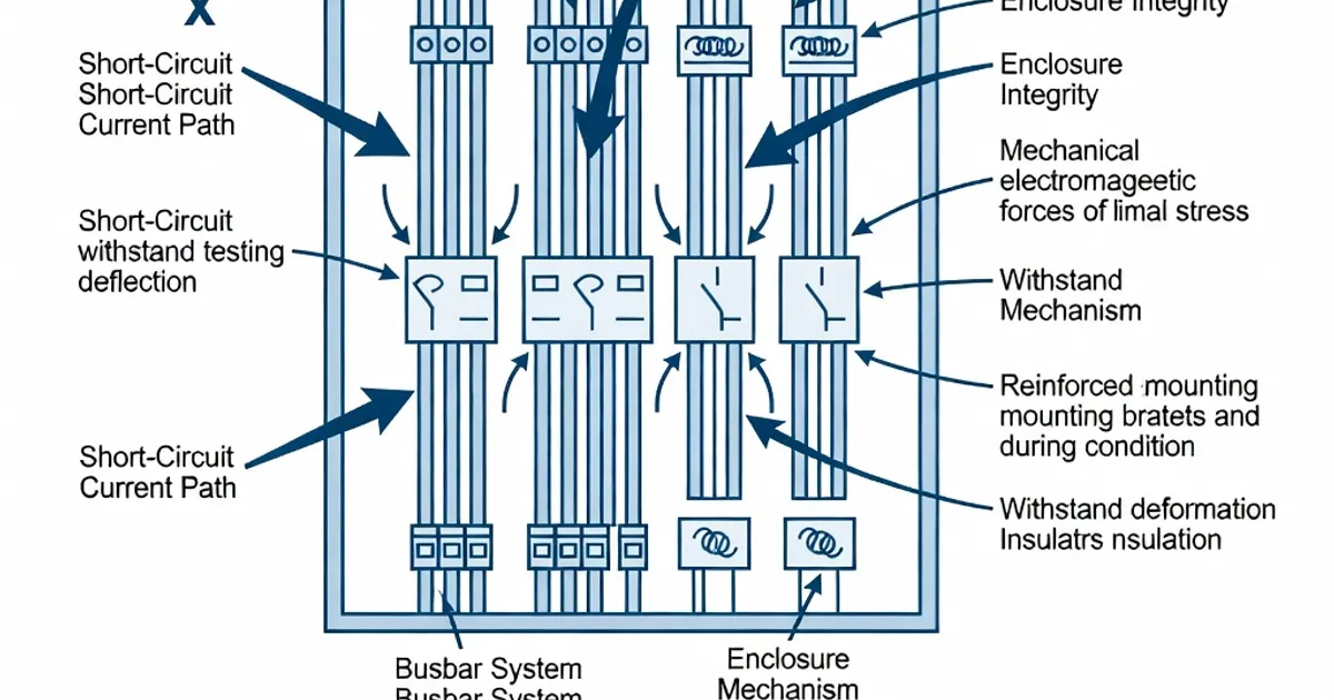
Verification must produce evidence that the assembly meets the defined ratings in the technical file. Tests record RMS and peak currents, mechanical deformation, loss of service continuity, emission of molten metal or arcing, and the post-test checks for IP and functionality [2][5].
Passing Criteria and Post-Test Requirements
The acceptance criteria in IEC 61439 emphasize safety and serviceability:
- No structural damage that impairs the assembly’s intended safe use or that would permit live parts to become accessible.
- No permanent reduction of the declared degree of protection (IP) — post-test IP must equal the pre-test declaration (IEC 60529 applies) [2].
- No loss of functionality of required devices and circuits; the assembly must be capable of carrying rated current and operating its protection/interlocking mechanisms after the test.
The standard excludes passive mechanical testing on power switchgear assemblies (PSC) in some cases and defines additional requirements specific to PSC in IEC 61439-2 [5]. Post-test inspections must include checks for continuity of service, torque of critical fasteners, absence of conductive splashes that could create new faults, and verification that cable entries and gland seals remain intact for IP preservation [2][5].
Busbar Mechanical and Thermal Considerations
Designers must address both thermal (I²t) and electrodynamic (Ipk-related) effects:
- Thermal stress: dimension busbar cross-section and connections so that I²t during the short-time withstand duration does not produce temperatures that damage insulation or mechanical fittings. As a rule, thermal energy is evaluated against materials’ allowable temperature rise and melting limits (I²t calculations) [1][3].
- Electrodynamic stress: dynamic forces between conductors scale with the square of the instantaneous current and act over the short-time interval around Ipk. Rigid supports, minimized conductor overhangs and robust bolted connections mitigate deflection and risk of contact separation [1].
Typical practical rules used by manufacturers include specifying copper busbars with regular supports at ≈200–300 mm spacing for high short-circuit ratings, using high-strength insulated supports and torque-controlled bolting to ensure consistent connection integrity [1][3]. Screws and supports must be specified to resist the calculated peak mechanical forces; failures in supports or loose screws are common root causes for assembly failures during tests [1][4].
Coordination with Short-Circuit Protective Devices (SCPDs)
When the assembly’s short-circuit withstand rating depends on an upstream SCPD, the critical parameter is the energy that the device allows to pass, expressed by its I²t or limiting characteristics. IEC 61439 requires verification of the assembly under the same limiting conditions that will exist in service [2][3]. Key points:
- SCPDs must be specified and mounted as they will be used in service. Tests that omit mounted SCPDs do not prove conditional withstand ratings.
- Surge protective devices (SPDs) and their required Isccr (service short-circuit current rating) must match the assembly’s expected limited fault current. DEHN guidance recommends matching SPD Isccr to the installation rating and verifying with the assembly’s conditional Iccr [4].
- Device standards (IEC 60947 series) define breaking and making capacities and I²t characteristics; the assembly verification must reference these device datasheets for coordinated assessment [6].
Short-Circuit Test Procedures and Instrumentation
When an assembly is subject to destructive or non-destructive short-circuit testing, the procedure follows a tightly controlled protocol per IEC 61439-1 Clause 10.11 and IEC 61439-2 where applicable. Typical steps and instrumentation include:
- Measurement of prospective fault current at the test location (RMS and peak) with calibrated current transducers and Rogowski coils or high-bandwidth CTs to capture Ipk.
- Mounting the assembly with final cover and accessories; where outgoing circuits are included they are fitted with the actual protective devices and conductors used in service to observe arc emissions and interaction effects [2][5].
- Recording mechanical deformations using high-speed cameras and post-test dimensional checks on busbars and supports; thermocouples may record temperature rise of insulation and materials.
- Post-test IP checks (water/dust ingress tests), dielectric tests and operation checks of protective devices to demonstrate unchanged functionality [2][5].
Manufacturers often provide test reports with detailed current-time traces, photographic evidence and mechanical inspection records suitable for inclusion in the assembly technical file and for third-party certification [1][3][5].
Manufacturer Examples and Typical Ratings
Leading switchboard manufacturers publish verified ratings achieved either by full testing or by documented reference-design programs. Typical published values include:
| Manufacturer | Product Line | Common Icw / Duration | Typical Ipk | Notes |
|---|---|---|---|---|
| Schneider Electric | Prisma | Up to 100 kA / 1 s | Up to 187 kA | Tested per IEC 61439-1 Clause 10.11; reference-design documentation available [1] |
| ABB | UniGear / LV switchboards | Typical 40–100 kA / 1 s (model dependent) | Varies | Workbook details busbar dimensioning and reference-comparison processes (see pages 73–77) [3] |
| Siemens | NXPLUS / Sentron (LV panel families) | 50–100 kA / 1 s common in LV ranges | Typical 100–200 kA | Follows IEC 61439-2 requirements; busbar supports and spacing are documented [2] |
| Eaton | Power Xpert UX | 50–100 kA / 1 s typical | 105–220 kA depending on configuration | Reference-design verification and SCPD coordination emphasized [2] |
| Rittal | Perforex VX / IT | Up to 100 kA / 1 s | Product dependent; arc-resistant options | Enclosures designed to maintain IP post-test; integrates IEC 60947 devices [5][6] |
Note: the published values depend on specific configuration, busbar material (copper vs aluminium), support spacing, enclosure stiffness and whether SCPDs are mounted. Always consult the manufacturer’s technical documentation for the exact tested configuration [1][3].
Design Best Practices
Industry experience and the standard point to consistent design and verification practices that reduce risk, cost and the need for full testing:
- Design for a margin: aim for Icw > calculated prospective fault current and Ipk margins that accommodate foreseeable system changes. Suppliers often target 100 kA / 1 s as a practical high-performance benchmark [1][3].
- Leverage a tested reference design: replicate or exceed the reference design’s busbar cross-sections, spacing, supports, fasteners and enclosure stiffness to justify comparison-based verification and avoid repeated full testing [2].
- Control screw torque and fastening practice: specify torque values and assembly procedures; loose or underspecified connections are a common cause of failure during short-circuit events [1][4].
- Coordinate SCPDs early: select circuit breakers and fuses with documented I²t and breaking capacities that protect the assembly and meet conditional Iccr requirements. Include SPD Isccr checks when surge devices are present [3][4].
- Minimize unprotected conductor lengths: reduce lengths of conductors that are not within the protected busbar trunk to avoid local hot spots or arcing during faults.
- Document everything: include assembly layout, busbar drawings, support placement, protection device datasheets and torque procedures in the technical file required by IEC 61439 [2].
Common Failure Modes Observed in Tests
Understanding frequent failure causes helps designers preempt them:
- Insufficient mechanical support for busbars leading to separation or weld/failure at joints under Ipk-induced forces.
- Loose or underspecified fasteners resulting in rapid heating and loss of connection under short-time currents.
- Incorrect SCPD selection where the device allows excessive I²t, producing thermal damage despite acceptable peak current ratings.
- Enclosure weakness that allows deformation or breaches that reduce IP rating or expose live parts after a fault.
- Inadequate documentation that prevents a successful reference-design comparison, forcing costly retesting [1][4][5].
Specification Table for Designers
Use this quick-reference specification table during procurement and design review to capture the minimum data required to assess short-circuit capability.
| Parameter | Typical Value / Requirement | Relevant Standard Clause |
|---|---|---|
| Rated short-time withstand current (Icw) | e.g., 50–100 kA / 1 s (specify) | <