Protection Coordination in Panel Assemblies
Selectivity and backup protection coordination for IEC 61439 panel systems.
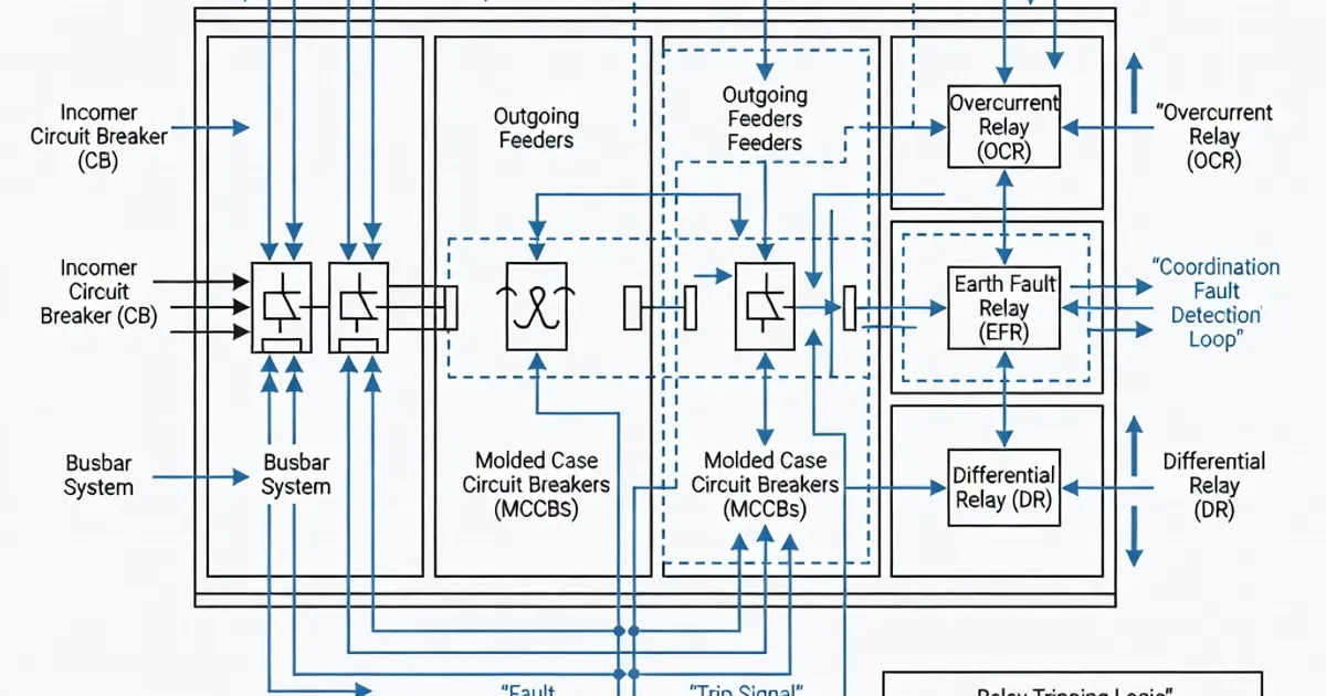
Protection Coordination in Panel Assemblies
This article describes protection coordination practices for IEC 61439-compliant low-voltage panel assemblies. It consolidates the normative requirements, verification methods, device coordination types, manufacturer toolsets, and practical design recommendations needed to achieve selective, reliable fault clearance while preserving assembly integrity. Where applicable the text cites IEC clauses and industry guidance documents to ensure traceable, standards-based implementation.
Scope and objectives
Protection coordination in an LV panel assembly has two primary objectives: selectivity (ensure the protective device immediately upstream of the fault isolates that fault without tripping upstream supply elements) and backup protection (ensure upstream protection clears the fault if the downstream device fails). Achieving both requires verifying short-circuit withstand of conductors and enclosures, ensuring continuity of protective bonding, managing temperature rise limits and preserving degrees of protection (IP/IK) after assembly and testing. These requirements are defined and verified in IEC 61439‑1 and the part-specific standards (e.g., IEC 61439‑2 for power switchgear and IEC 61439‑3 for distribution boards) and are applied in conjunction with device standards in the IEC 60947 family.
Standards and normative references
- IEC 61439‑1:2020 — Common specifications: specifies verification methods for short-circuit withstand and coordination impacts; see Clause 10.10 (short-circuit verification), Clause 10.9 (temperature rise) and Clause 10.11 (protective conductor/earth continuity) [1].
- IEC 61439‑2:2020 — Power switchgear and controlgear assemblies: applies additional requirements where switching devices and motor starters require specific coordination and Type‑classification alignment with IEC 60947 series [1][2].
- IEC 61439‑3:2024 — Distribution boards: updates relating to integration, IP/IK and verification for modular distribution assemblies; adopt the 61439‑1 verification approach [3].
- IEC 60947 series — Device standards (circuit-breakers, contactors, starters): define Type‑1/Type‑2 coordination characteristics and device short‑circuit behaviour used in selectivity studies, notably IEC 60947‑2 and IEC 60947‑4‑1 [2][5].
- IEC 60529 — Degrees of protection by enclosures (IP codes): used to verify that proposed protective arrangements do not reduce ingress protection below specified levels after assembly and tests [1][3].
- IEC 62262 — IK mechanical impact codes: relevant where mechanical protection (e.g., IK08) is specified for the enclosure [2][3].
Short‑circuit withstand, peak currents and electrical integrity
IEC 61439 requires panel assemblies to demonstrate sufficient mechanical and thermal strength to withstand specified prospective short-circuit currents. The standard prescribes verification against both rated short-time withstand current (Icw) and peak (prospective) current (Ipk), and requires assessment for the main circuit conductors, neutral and protective circuits. The typical verification values used in practice are:
| Parameter | Requirement / Typical Value | Reference |
|---|---|---|
| Rated short-time withstand current (Icw) | Verified for the prospective short-circuit current for a duration (commonly 1 s for LV switchgear) | IEC 61439‑1 Clause 10.10 [1] |
| Peak prospective current (Ipk) | Assembly must withstand dynamic effects of Ipk (values depend on system X/R; examples in product literature show Ipk up to 220 kA for some ACBs) | IEC 61439‑1 / manufacturer data [1][4] |
| Protective bonding continuity | Resistance of protective conductor joints typically < 0.1 Ω after short‑circuit tests (continuity must be proven) | IEC 61439‑1 Clause 10.11 [1] |
| Terminal temperature rise | Max temperature rise commonly limited to 70 K at terminals under rated current (verify per Clause 10.9) | IEC 61439‑1 Clause 10.9 [1] |
| Degrees of protection (IP) | Preserve indicated IP rating (e.g., IP2XC min. for basic access protection; distribution boards often IP41/54 etc.) | IEC 61439‑1 Clause 8.2 / IEC 60529 [1][3] |
Verification may be performed by direct type tests (dynamic short‑circuit tests), peak current tests, temperature rise tests or by comparison to a reference design that has been tested under equal or more restrictive conditions (per IEC 61439‑1) [1]. Manufacturers commonly publish tested reference designs and libraries that allow assembly verification by comparison rather than repeating full dynamic tests for each custom configuration.
Neutral and protective conductor considerations
Neutral conductors can carry significant short‑circuit currents in unbalanced faults and must therefore be sized, routed and verified with the same rigor as phase conductors. Protective bonding conductors and structural earth must demonstrate continuity and mechanical integrity after dynamic short‑circuit stresses; IEC 61439‑1 requires verification of continuity and acceptable resistance (commonly <0.1 Ω) and explicit short‑circuit testing where applicable [1].
Coordination types: Type 1 vs Type 2 and device selection
IEC 61439 references the IEC 60947 device family for coordination behaviour. Two coordination types relevant to panel assemblies are:
- Type 1 coordination — The assembly must not present a hazard and must permit replacement of parts after a short‑circuit; damage may occur but must be repairable. Typically acceptable where replacement downtime is tolerated [2].
- Type 2 coordination — The assembly must not suffer damage and the circuit shall be restorable immediately after a fault. Type 2 is the preferred classification for circuits supplying rotating machines, contactors and starters per IEC 60947‑4‑1 requirements, where abnormal service must be minimized [2].
For motor circuits and starter assemblies, designers commonly require Type 2 coordination between fuses and contactors so that contactors are not damaged by upstream fuse clearing. IEC 60947‑4‑1 provides device-level requirements that enable Type 2 coordination by specifying the limiting characteristics (let-through current, energy) of fuses and the withstand capabilities of contactors [2].
Verification methods for panel assemblies
IEC 61439‑1 allows three principal verification routes for short‑circuit strength and coordination:
- Type tests — Full dynamic short‑circuit tests on the assembly to measure Icw and Ipk performance directly. This is the definitive method but costly for custom panels.
- Comparative verification — Demonstrate that the assembly is equivalent or superior to a tested reference design (same conductor sizes and busbar arrangements, similar enclosure and support). This is commonly used in industrial practice to avoid repeated destructive testing [1].
- Calculation and device data — Use device manufacturers’ time‑current curves, selectivity tables and conductor thermal models to demonstrate selectivity and proper withstand, often supplemented by partial testing (temperature rise) where required [1][4].
Manufacturers and system integrators frequently combine comparative verification with software simulation to confirm selectivity margins. Product literature and manufacturer libraries (e.g., ABB SACE, Siemens SIMARIS, Schneider EcoStruxure) include tested reference scenarios and device characteristics to streamline verification [5].
IP, IK and temperature verification
Verification is not limited to electrodynamic tests. IEC 61439 requires confirmation that temperature rise limits are not exceeded at terminals and connecting parts (Clause 10.9) and that the declared degree of protection (IP) and mechanical impact resistance (IK) are preserved after assembly and testing (Clauses 8.2 and relevant product standards) [1][3]. The updated IEC 61439‑3:2024 emphasizes enclosure protection for distribution boards where integrated devices and wiring can affect declared IP/IK [3].
Design best practices for protection coordination
Practical engineering follows these established best practices to achieve reliable coordination while complying with IEC 61439:
- Prioritize selectivity and documented margins — Use manufacturer time‑current curves and software to achieve at least 100% selectivity where required (i.e., the upstream device interrupts later than the downstream device for all fault currents within the intended range). Simulate both phase and ground faults and verify with conservative margins [2][5].
- Prefer Type 2 coordination for motor/starter circuits — Specify Type 2 coordination per IEC 60947‑4‑1 for contactors and motor circuits; label the maximum fusing values that achieve Type 2 behaviour (e.g., "Maximum fuse rating for Type 2 protection: XX A") [2].
- Use validated reference designs — Where possible, base panel designs on manufacturer reference assemblies that have known short‑circuit test results; this reduces the need for full dynamic testing [1][4].
- Maintain PE continuity and low resistance — Design protective conductor routing and mechanical bonding to ensure continuity after dynamic events; target <0.1 Ω for bolted connections where required by verification [1].
- Account for neutral fault currents and asymmetry — Size neutral conductors for prospective fault currents; verify their mechanical and thermal withstand as part of the assembly [1].
- Respect temperature rise and derating — Consider thermal effects of selected protective devices (e.g., MCCBs and fuse holders) and ensure terminal and busbar temperature rise remains within the 70 K limit where applicable under rated current [1][4].
- Document assumptions and limits — Record short-circuit levels used for verification, device curve files, cable/connector ratings and any limits (IP, IK, service conditions) to preserve traceability during commissioning and maintenance.
Manufacturer toolsets, products and examples
Major switchgear and panel vendors provide device libraries and software that simplify coordination studies and panel verification. These tools incorporate tested device characteristics and reference designs, enabling efficient selectivity and withstand assessments:
| Brand | Product / Tool | Key coordination capability |
|---|---|---|
| Siemens | NXPLUS C, 8DJH; SIMARIS Design | Type 2 coordination support; selectivity studies with device libraries; Icw examples up to 50 kA/1 s in typical tested designs [5] |
| ABB | UniGear ZS1, ReliaGear; SACE library | Documented short‑circuit withstand for assemblies (Icw up to 50 kA); selection and coordination via ABB libraries [5] |
| Schneider Electric | Okken, PrismaSe MT; EcoStruxure Power Design | Curve‑based selectivity, Type 2 coordination with Masterpact and ComPact ranges; high rated breaking capacities documented (up to 100 kA for some ACBs) [5] |
| Eaton | Power Xpert, TR 61439 guidance | Coordination charts and TR‑61439 based verification; published Ipk values for ACBs (examples up to 220 kA peak in product literature) [4] |
| Rittal | Perforex VX25 enclosures | Enclosures designed for IEC 61439‑2 assemblies; IP55 options and integration partnerships with device vendors for coordinated solutions [4] |
These vendor ecosystems reduce engineering risk by providing pre‑tested modules and validated device parameters that integrate into verification workflows. For example, Siemens SIMARIS and Schneider EcoStruxure allow calculation of selectivity margins and temperature rise with manufacturer-provided device curves, easing compliance to IEC 61439 verification clauses [5].
Common pitfalls and risk mitigation
- Overlooking neutral short-circuit contributions — Designers sometimes omit neutral fault currents in selectivity simulations; include unbalanced and neutral fault scenarios to prevent undersizing neutrals or misjudging coordination.
- Assuming device label ratings equal assembly withstand — A device’s breaking capacity does not automatically guarantee the assembly’s electrodynamic withstand; verify busbar supports, insulation spacing and enclosure strength per IEC 61439‑1 [1].
- Neglecting protective conductor routes — PE continuity and bonding clamps can fail under dynamic forces if not adequately designed; use measured resistance targets and robust mechanical fixing to mitigate this risk [1].
- Insufficient documentation — Failure to record reference designs, test reports and device curve sources complicates future modifications and jeopardizes traceability required by IEC 61439.
- Ignoring temperature rise interactions —
Related Panel Types
Frequently Asked Questions
Request a Quote
Tell us about your panel requirements and our engineering team will get back to you within 24 hours.
Email Us
[email protected]Call Us
+90 232 332 22 78