Power Factor Correction Panel Design Guide
Design principles and component selection for automatic PFC panel assemblies.
Power Factor Correction Panel Design Guide
This guide consolidates the technical requirements, design best practices, verification procedures, and product considerations necessary to design IEC 61439-compliant low-voltage Power Factor Correction (PFC) panels. It targets electrical designers, panel builders, and project engineers responsible for specifying and verifying shunt capacitor-based compensation assemblies installed in commercial and industrial distribution systems. The guidance references the IEC 61439 series and complementary standards for capacitors, switching devices and enclosure requirements, and includes worked examples and specification tables to support practical design decisions.
Overview: Purpose and Function of PFC Panels
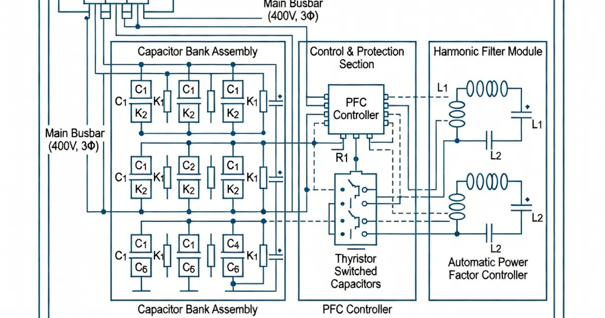
Power Factor Correction (PFC) panels improve distribution efficiency by supplying leading reactive power locally, thereby reducing apparent power draw from the upstream supply and improving cosφ toward a target (commonly >0.95). A typical PFC assembly uses fixed or switched shunt capacitors, detuned reactors (DR), switching contactors or static compensators, fuses or circuit breakers for protection, and a controller to manage switching stages. Designers must address thermal performance, short-circuit withstand, dielectric clearances, harmonics and resonance risk, and neutral sizing in accordance with IEC 61439 and associated component standards (IEC 60831, IEC 60947, IEC 60529). See IEC 61439-1 and IEC 61439-2 for the mandatory verification framework and manufacturing declarations (see [1], [2], [3]).
Applicable Standards and Normative References
Key standards governing design and verification of PFC panels include:
- IEC 61439-1 and IEC 61439-2 — General rules and power switchgear assemblies: specify verification methods for temperature rise (Clause 10.10), short-circuit withstand (Clauses 8.6 and 10.9), routine and type tests, marking and documentation requirements (Clauses 11.x) [1][2].
- IEC/EN 60831-1/-2 — Shunt power capacitors: define capacitor ratings, permissible operating voltages, losses, and harmonic considerations for PFC capacitors [3].
- IEC 60947 series — Low-voltage switchgear and controlgear for selection of contactors and switching devices appropriate for capacitor switching duty [3].
- IEC 60529 — Degrees of protection (IP codes), relevant to enclosures with forced ventilation needed for capacitor cooling [3].
- Supplemental manufacturer guides and industry application notes (e.g., Schneider Electric PFC design guide, ABB and Siemens technical workbooks) provide practical design examples and vendor-specific component recommendations [3][5][7].
Design Objectives and Ratings to Specify
At project inception document the following rated values on the assembly specification and nameplate. These values drive verification and component selection per IEC 61439:
- Un — Rated voltage of the assembly (example: 400 V or 690 V).
- Ue — Rated operating voltage of the assembly (example: 230 V control circuits, 400 V power circuits).
- Ui — Rated insulation voltage (example: 800 V as commonly used for LV switchgear) [1][2].
- Uimp — Rated impulse withstand voltage (for LV panels typically 4–6 kV depending on system and equipment) [1].
- InA — Rated current of the assembly (select based on sum of outgoing circuit currents and rated diversity factor, see below).
- Isc, Icw, Ipk — Prospective short-circuit current at supply (conditional Isc), rated short-time withstand current (Icw, e.g., 15 kA/1 s typical for fused systems), and peak current Ipk used for electrodynamic verification (Ipk = Icw × n per IEC 61439-1 Table 7) [1][2].
Key Design Parameters and Calculation Methods
Rated Diversity Factor (RDF) and Assembly Rated Current (InA)
IEC 61439 requires designers to determine the assembly rated current InA based on the sum of rated currents of all outgoing circuits multiplied by a chosen Rated Diversity Factor (RDF). Typical RDF values for switched capacitor banks are between 0.6 and 0.8 depending on expected simultaneity; a commonly used conservative value is 0.7. Example:
- Three outgoing capacitor stages each rated Inc = 200 A, RDF = 0.7 → InA = 3 × 200 A × 0.7 = 420 A. Designers then select busbars, cables and protective devices rated ≥420 A and apply the safety margin/derating described below [1][2][4].
Thermal (Temperature Rise) Verification — IEC 61439-1 Clause 10.10
Verify temperature rise of current-carrying conductors and adjacent non-metallic parts using one of the permitted methods: (a) unit tests on a prototype (type test), (b) calculation using validated methods and reference design comparison (permitted up to defined ratings), or (c) comparison with a tested reference assembly. Key constraints include:
- Limit the temperature rise of non-metallic parts so that their surface temperature does not exceed 70 K above an ambient test temperature of 35 °C (i.e., max surface ~105 °C) unless the materials are rated higher [1][2].
- For current ratings up to 1600 A the manufacturer may use calculation methods and reference-tests with a conservative 20% derating margin on calculated losses to stay within verified envelopes [2][5].
- Power dissipation (PV) must be calculated for each outgoing circuit and assembly items. For example, an NH00 fuse base (160 A) dissipates approximately 4.2 W per pole at rated current — sum these contributions to determine total PV for the enclosure heat balance [2][5].
Short-Circuit and Electrodynamic Verification — IEC 61439-1 Clauses 8.6 & 10.9
Design for the prospective short-circuit at the point of supply. Verify:
- Electrical clearances and dielectric strength via dielectric tests (Clause 11.9) and by selecting insulation ratings Ui and Uimp appropriate for the network [1].
- Thermal withstand (Icw) — capability to withstand rated short-time currents for the specified duration (commonly 1 s for LV assemblies with fuses, e.g., Icw = 15 kA/1 s for many designs) [1][2].
- Electrodynamic withstand (Ipk) — peak mechanical forces during fault conditions. Compute Ipk from Icw and appropriate multiplication factors per IEC 61439-1 Table 7; ensure busbar supports, fixings and enclosures resist these forces [1][2].
Neutral Conductor Sizing
Follow IEC 61439-2 sizing rules for neutrals in PFC assemblies: provide a neutral conductor sized at 100% of the phase conductor cross-section up to 16 mm², and 50% above 16 mm² (but never less than 16 mm²). This ensures adequate neutral capacity for unbalanced harmonic currents often present in compensated networks [4].
Component Selection and PFC-Specific Considerations
Capacitors
- Specify shunt capacitors conforming to IEC/EN 60831-1/-2. Choose rated voltage to match system Un and account for harmonic overvoltages and expected ambient temperatures. Use capacitors with rated current and permissible ripple to handle expected harmonics [3].
- Locate capacitors to maximize ventilation and avoid close proximity to heat sources (e.g., detuned reactors) to limit capacitor temperature rise and prolong life [3].
Detuned Reactors (DR) and Harmonic Management
Detuned reactors prevent resonant amplification of harmonics and limit the circulating harmonic current between the capacitor bank and the supply. Common detuning ratios are 7% (typical for strong harmonic environments) and 14% for less aggressive detuning. For 50 Hz systems 7% detuning places the reactor resonance near 189 Hz (3.78 × 50 Hz), reducing amplification of the 5th and 7th harmonics; consult manufacturer harmonic tables when selecting DR sizes [3]. DRs must be sized for thermal and short-time overloads and should incorporate temperature monitoring where applicable to disconnect capacitors if overheating is detected [3].
Switching Devices and Protection
- Use contactors or vacuum switching devices rated for capacitor switching duty; IEC 60947 guidance applies. Capacitor switching involves inrush currents and possible switching transients — select devices with appropriate making/breaking capacities and use anti-reclosing logic to protect capacitors and contactors [3].
- Fuses (gG/gL) are commonly used for short-circuit protection of capacitor units. Fuse selection must consider prospective short-circuit currents and the capacitor's withstand characteristics; typical fuse ratings for capacitor protection are coordinated to clear faults without causing undue service interruptions [3][5].
Enclosures and Ventilation
Capacitors and DRs generate heat; ensure adequate natural or forced ventilation in accordance with IEC 60529 IP degree expectations and vendor cooling recommendations. Enclosure design must balance ingress protection against environmental contaminants and heat dissipation requirements — many manufacturers provide enclosure modules specifically optimized for PFC modules (e.g., Rittal systems) [3][2].
Layout, Wiring and Mechanical Design Best Practices
- Keep capacitor units and detuned reactors physically separated to reduce heat transfer. Provide dedicated ventilation paths and remove hot spots with perforated panels or fan-assisted extraction where necessary [3].
- Minimize conductor lengths from the capacitor to the switching device and fuse (max. recommended unprotected conductor run often 3 m) to reduce distributed impedance and harmonic heating [3][5].
- Provide robust busbar supports and mechanical bracing sized for the calculated electrodynamic forces (Ipk) under fault conditions per IEC 61439–1 guidance [1][2].
- Label circuits clearly and provide a nameplate showing Un, Ue, Ui, InA, Icw and other mandatory information per Clause 11 (marking and documentation) [1].
Verification, Testing and Routine Checks
Follow the verification and testing regime mandated by IEC 61439:
- Type tests (where required): thermal tests, short-circuit withstand tests, dielectric tests and verification of protection against electric shock according to the relevant Clauses of IEC 61439-1/2 [1][2].
- Routine tests performed on each manufactured assembly: continuity of protective circuits (<10 A test current as specified in Clause 11.4), dielectric testing at routine voltage (Clause 11.9), visual inspection and functional checks of controllers and switching devices [1].
- Provide complete documentation: schematic diagrams, installation instructions, rated values and the EC declaration of conformity as required by Clause 11. These documents support field acceptance and future maintenance [1][2].
Harmonics, Resonance and Practical Remedies
Harmonic currents from nonlinear loads (variable speed drives, rectifiers) can cause capacitor overheating, increased losses and resonance. Address harmonics as follows:
- Calculate harmonic spectrum of the site and perform impedance studies prior to specifying detuning levels. Use DRs sized to give detuning at 7% or 14% depending on harmonic severity; 7% detuning places resonance above the 3rd harmonic region reducing risk to the 5th and 7th harmonics (approx. 189 Hz for 50 Hz systems) [3].
- Where harmonics are severe consider tuned filters or active compensation solutions (static VAR compensators) rather than simple shunt capacitors [3].
- Include temperature monitoring on DRs and capacitors and automatic disconnection thresholds to prevent thermal runaway in the presence of excessive harmonic heating [3].
Example Calculations
Example: sizing InA and applying derating.
- Load: four capacitor stages, each Inc = 150 A. Select RDF = 0.7 (conservative). Sum = 4 × 150 A × 0.7 = 420 A → choose busbars and main protective device InA ≥ 420 A.
- Apply a 20% safety/derating margin as recommended when using calculation-based temperature verification (420 A × 1.20 = 504 A). Select standard InA = 525 A or 630 A as appropriate to meet vendor availability and standard busbar ratings [2][5].
- Short-circuit check: prospective Isc at supply = 70 kA (conditional). If Icw for the selected assembly = 15 kA/1 s and IEC multiplication factor for Ipk yields required peak, verify busbar supports and connection hardware are specified to withstand the resulting electrodynamic forces per IEC 61439-1 [1][2].
Specification and Comparison Table: Typical PFC Panel Parameters and Vendor Features
| Parameter / Vendor | Schneider Electric | ABB | Siemens | Typical Value / Comment |
|---|---|---|---|---|
| Rated Assembly Voltage (Un) | 400–690 V | 400–690 V | 400–690 V | Specify per project; Ui commonly 800 V |
| Detuning Options | 7% / 14% DR modules | 7% / 14% detuned solutions | <