Motor Starting Methods in Panel Assemblies
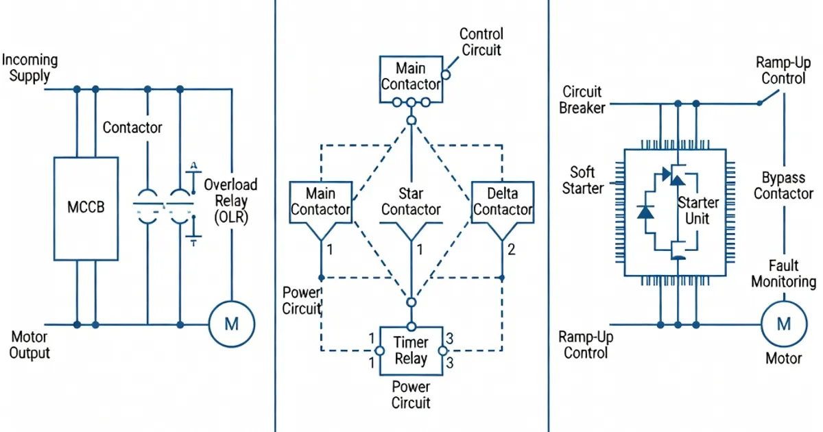
Comparison of DOL, star-delta, soft starter, and VFD motor starting methods.
Motor Starting Methods in Panel Assemblies
This article explains the most common motor starting methods used inside low-voltage (LV) panel assemblies, the effects of starting on panel verification per IEC 61439, and practical design and selection guidance for switchgear and motor control centers (MCC). It consolidates technical values, applicable IEC clauses, and modern product practice so designers and specifiers can verify assemblies for temperature rise, short-circuit withstand, and coordination during motor starting events.
Overview: Why starting method matters for IEC 61439 panels
Motor starting introduces transient currents and torque that affect temperature rise, busbar and terminal ratings, protection selectivity, and mechanical stresses inside a panel assembly. Different starting methods produce widely different inrush currents and torque: Direct-On-Line (DOL) can reach 600–800% of full-load current (FLC), while modern electronic methods (soft starters and VFDs) limit inrush to a few hundred percent or less. IEC 61439 verification must therefore consider these currents when assessing temperature-rise, short-circuit coordination and the ability of components and conductors to survive repetitive starts and switching events. Verification may be by test, calculation, or comparison per IEC 61439-1 (Ed. 3.0) and associated product-part standards for starters and drives [IEC 61439-1 clauses 10.10–10.11] [5][6][9].
Applicable standards — the normative framework
- IEC 61439-1:2020 — General rules for low-voltage switchgear and controlgear assemblies; verification by test, calculation or comparison; temperature-rise and short-circuit verification requirements. See Clause 10 (verification) and Annexes for user schedules [IEC 61439-1:2020] [5][6][9].
- IEC 61439-2:2021 — Particular requirements for power switchgear and MCCs, relevant for motor distribution compartments.
- IEC 60947-4-1:2020 — Requirements for contactors and motor starters (utilization categories AC-3, AC-4 and frequency of operations, coordination Type 2 expectations) [2].
- IEC 61000 family and IEC 61800-5-1 — EMC, harmonic emission guidance (important for VFDs), and safety requirements for adjustable speed drives [9].
- IEC 60529 and IEC 62271-200 — Enclosure protection (IP) and impact (IK) ratings applied to panel design; IEC 61439-1 Clause 10.12 cross-references mechanical impact requirements for compartments [3].
Primary motor starting methods and their electrical characteristics
Below are the principal starting methods used in LV panel assemblies, with typical numeric ranges and the IEC requirements that designers must apply during verification.
Direct-On-Line (DOL)
Principle: Apply full line voltage directly to the motor. Simple contactor and overload protection.
- Typical starting current: 6–8 × FLC (600–800% FLC) for typical induction motors at 400V. Peak asymmetrical currents can be higher for a few cycles [1][2].
- Starting torque: ~100–150% of rated torque; highest mechanical stress among common starts.
- Components: Contactors rated for AC-3 utilization per IEC 60947-4-1; overload relays sized for full-load protection and locked rotor capability [2].
- IEC verification drivers: Temperature-rise checks per IEC 61439-1 Clause 10.10; short-circuit coordination and withstand per Clause 10.11. Terminals commonly limited to ΔT ≤ 70 K and average conductor rise checks to 105 K depending on material and reference temperature [3][6].
- Application guidance: DOL remains cost-effective and acceptable for small motors (commonly <10 kW) where inrush and mechanical stress are tolerated.
Star‑Delta (Wye‑Delta)
Principle: Start the motor in star (wye) connection to reduce starting voltage to each phase (≈1/√3 of line voltage), then switch to delta for running.
- Typical starting current: During the star period ~150–250% FLC; a transient spike occurs at the star→delta transfer if not managed, so designers must account for that switching current [1].
- Starting torque: ≈33% of rated torque in star; full torque after transfer to delta.
- Components: Three contactors (main, star, delta) and a timer or transfer device. Contactors selection per IEC 60947-4-1 (class specified for switching frequency and number of operations — e.g. Class 12 cycles/hour in some references) [2].
- IEC verification drivers: Temperature-rise and mechanical strength (Clause 10.5) for changing switching sequences; short-circuit coordination to ensure safe transfer (Clause 10.11) [3].
- Application guidance: Suitable for medium-power motors where reduced starting torque is acceptable. Consider additional inrush at transfer and provide interlocks to prevent closed transition if not permitted.
Soft Starter (Electronic starting)
Principle: Use thyristor-based or IGBT-based circuits to gradually apply voltage (and therefore torque) to the motor during ramp-up, then bypass with a mechanical contactor for steady-state running.
- Typical starting current: Controlled to roughly 200–400% FLC depending on ramp settings and torque requirements.
- Starting torque: Adjustable from low values up to full torque; many products provide torque boosting features (100–200% depending on device and settings) [4].
- Components and arrangements: Soft starter module plus a bypass contactor (to reduce losses in steady-state). Ensure the bypass device is properly coordinated and interlocked to avoid circulating currents during the start-to-bypass transfer.
- IEC verification drivers: Temperature-rise assessments must consider continuous dissipation in the starter and bypass device; conductor derating and enclosed cable lengths per IEC 61439-1 Clause 8.6 (non-protected conductors ≤ 3 m guidance) apply when calculating temperature rise and grouping effects [4][3].
- Application guidance: Soft starters are standard up to large motor sizes (many manufacturers supply up to 1200 kW or greater). Designers should ensure bypass contactors are Type 2 coordinated where required and that the startup settings are considered in panel loss and ventilation calculations.
Variable Frequency Drives (VFDs) / Adjustable Speed Drives
Principle: Provide controlled voltage and frequency to the motor, enabling smooth start, speed control and energy savings.
- Typical starting current: Limited and controlled; typical inrush often <150% FLC in ramp-based starts, though inrush depends on ramp time and torque demands.
- Torque control: 0–150% or more of rated torque available depending on control strategy; full torque at low speed with field-oriented control on modern drives.
- Harmonics and EMC: VFDs generate harmonics; compliance with IEC 61000-3-12 (network harmonic limits) and EMC filters may be required. Drive selection must consider harmonic mitigation (dV/dt filters, DVRs, multi-pulse rectifiers) per site constraints [9].
- IEC verification drivers: Panel power loss and temperature-rise verification must include VFD losses and possible forced-ventilation. Reference design or testing required if drives are grouped in a compartment per IEC 61439-1 Clause 10.10 [3][5]. Drive safety per IEC 61800-5-1 applies for electrical safety requirements [9].
- Application guidance: VFDs are preferred for high-power motors (commonly >50 kW) when process control or energy savings justify the up-front cost. Proper harmonic and thermal management is essential in panel design.
Comparison Table: Starting Method Characteristics and IEC Links
| Method | Starting Current (%FLC) | Starting Torque (%Rated) | IEC Clauses / Standards | Typical Application |
|---|---|---|---|---|
| DOL | 600–800% | 100–150% | IEC 61439-1 Clause 10.10, IEC 60947-4-1 (AC-3) | Small motors <10 kW; simple, low-cost |
| Star‑Delta | 150–250% (star); spike at transfer | ~33% (star), 100% (delta) | IEC 61439-1 Clauses 10.5, 10.10; IEC 60947-4-1 | Medium motors where reduced torque ok |
| Soft Starter | 200–400% | 100–200% (adjustable) | IEC 61439-1 Clause 8.6/10.10; IEC 60947-4-1 | Medium-to-large motors; reduced mechanical stress |
| VFD | <150% (typical) | 0–150% (or higher) | IEC 61439-1 10.10; EMC standards IEC 61000 series; IEC 61800-5-1 | High-power motors, speed control, energy savings |
Verification and calculation considerations per IEC 61439
IEC 61439-1 requires assemblies to be verified for temperature rise, dielectric and mechanical strength, and short-circuit withstand. Designers may use testing, calculation or comparison methods; testing is preferred but calculations and comparisons are permitted within limits. Key practical points:
- Verification modes: Test, calculation (limited applicability), or comparison. Calculations for temperature-rise are normally restricted to assemblies up to certain ratings (e.g. commonly applied calculation limits are around 1,600 A in practice) and require conservative derating (≈20%) to account for uncertainties [3][9].
- Reference Design Factor (RDF): The RDF (or grouping factor) is used to transform installed currents to design currents (Ing = Inc × RDF). KEMA and other guidance explain RDF usage to ensure that grouped loads do not exceed tested arrangements [9].
- Temperature-rise limits: IEC 61439-1 Clause 10.10 sets permissible temperature rises for conductors, terminals and enclosures. Terminal rises often limited to 70 K above reference; average rises and insulation class limits drive conductor sizing and ventilation decisions [3][6].
- Short-circuit coordination: Starting events must be considered with respect to protective device coordination (Type 1/2 coordination). Starters and contactors should be selected and coordinated according to IEC 60947 series; upstream overcurrent protective devices (fuses or MCCBs) must be specified to prevent nuisance operation while ensuring safety under true faults [2].
- Derating and thermal management: For VFD bays and enclosed components, forced ventilation or heat-exchange provisions often become necessary to meet the ΔT limits. Designers typically allow for a 20% derating margin in calculations to account for ambient variation and grouping [3][6].
Enclosure, segregation and mechanical requirements
Panel enclosures must meet IP and IK requirements appropriate for the installation. IEC 60529 provides IP classifications; IEC 61439-1 Clause 10.12 requires impact resistance assessments referencing IK ratings (commonly IK08 or higher for industrial switchgear) and mechanical strength per IEC 62271-200 [3]. Segregation forms (e.g. Form 4b) for motor compartments are recommended to isolate starters, contactors and power conductors to minimise risk during maintenance and to aid compliance with short-circuit fault withstand and accessibility requirements.
Industry product examples and common capacities
Major manufacturers provide starter and drive ranges sized for integration into IEC 61439 assemblies. Representative product characteristics and practices observed in vendor literature:
- Siemens: SIRIUS soft starters and large 3RW series provide soft-start capabilities up to hundreds of kW and are commonly integrated with NXPLUS and SIVACON MCC systems. Devices include bypass contactors and are specified to reduce steady-state losses; Siemens application notes and design manuals provide coordination examples for IEC 61439 verification [7].
- ABB: PSE softstarters available up to large currents (150–2900 A), with torque control and bypass schemes. ABB technical guides provide loss-calculation worksheets used for IEC 61439 temperature-rise comparison verifications [4].
- Schneider Electric: Altistart soft starters and TeSys DOL starters up to large sizes; builder panels (e.g., Prisma) provide Type 2 coordination and MCC integration examples [2].
- Eaton, Rittal and others: Provide integrated enclosure and ventilation solutions, starter modules and VFD bays with verified temperature-rise dossiers for IEC 61439 assemblies.
Manufacturers typically supply verification dossiers (test reports, loss tables, RDF guidance) to support panel builders in assembling an IEC 61439-compliant documentation package [4][9].
Design best practices — practical rules of thumb
- Match starting method to application: Use DOL for small motors where mechanical stress and inrush are acceptable; use soft starters or star‑delta for mid-range motors to reduce mechanical load; select VFDs for high-power motors requiring control and energy savings (>50 kW is a common threshold in industry practice) [1][4].
- Account for transfer spikes: Star‑delta transfers can create transient spikes. Provide interlock sequencing and consider closed
Related Panel Types
Frequently Asked Questions
Request a Quote
Tell us about your panel requirements and our engineering team will get back to you within 24 hours.
Email Us
[email protected]Call Us
+90 232 332 22 78