Hospital Electrical System Design
Electrical distribution design for hospitals and healthcare facilities.
Hospital Electrical System Design
High-reliability hospital electrical systems require engineered low-voltage assemblies that deliver continuous power, rapid fault protection, and thermal stability under sustained loads. These switchgear and distribution assemblies are designed, verified and documented to IEC 61439 series requirements and complementary standards so that critical clinical, life-safety and IT equipment remain available and safe during normal operation and fault events.
Design Objectives for Hospital Power
- Supply continuity: restore or maintain power to essential loads with minimum interruption through redundancy, selective protection and segregation.
- Personnel and patient safety: ensure protective circuit effectiveness, equipotential bonding and proper RCD/earth-fault protection to limit shock and fire risk.
- Thermal stability: prevent hotspots, thermal runaway and insulation ageing by sizing busbars, conductors and ventilation to meet IEC 61439 temperature-rise criteria.
- Fault withstand: ensure assemblies maintain structural integrity, extinguish internal arcs and limit propagation after short-circuit faults.
- Serviceability and documentation: provide segregation for maintenance, clear labelling and the test documentation required by IEC 61439 Annex C.
Applicable Standards
Design and verification for hospital low-voltage assemblies must reference the IEC family and complementary standards:
- IEC 61439-1: General rules for design, type testing and verification (includes Clauses 10.x for type tests and Annex C for documentation).
- IEC 61439-2: Specific rules for power switchgear and controlgear assemblies (PSC) — used for hospital mains and primary distribution.
- IEC 60947 series: Requirements for circuit-breakers, contactors and other switching devices used within assemblies.
- IEC 60529: Degrees of protection (IP codes), required for control rooms, cleanrooms and clinical areas.
- Relevant guidance: IEC 60204-1 for machine/equipment interfaces and IEC 62271 for upstream high-voltage interfaces where applicable.
These standards combine to control design parameters such as rated current, short-circuit withstand, dielectric strength (Uimp), clearances and creepage, degree of protection and thermal limits (see sections below for clause-level detail).
IEC 61439 Type Tests and Key Clauses for Hospitals
IEC 61439-1 mandates a set of type tests that manufacturers must perform or verify during design validation. For hospital applications the most consequential clauses and requirements are:
Temperature-rise limits — Clause 10.10
Per IEC 61439-1 Clause 10.10, busbars and functional units are tested at rated current using the rated diversity factor (RDF) declared for the assembly. Tests assume an average ambient air temperature not exceeding 35 °C. Temperature-rise limits are expressed in Kelvin (K) and are specified to prevent local hotspots that accelerate insulation ageing or precipitate internal arc events. Design practice for hospitals includes derating where ambient or installation conditions exceed the reference, and verification with full enclosures and partitions fitted to replicate installed conditions (covers, doors, cable entries) as required by the standard [IEC 61439-1 Clause 10.10].
Dielectric properties — Clause 10.9 (Uimp and withstand)
IEC 61439-1 Clause 10.9 requires power-frequency and impulse withstand tests to confirm clearances, creepage and insulation coordination. Assemblies for clinical environments must be specified with an appropriate impulse withstand level (Uimp) compatible with Overvoltage Category III applications described in Annex G of IEC 61439. Manufacturers typically select Uimp to match the hospital site's transient environment and the device ratings used inside the assembly (consult device datasheets and upstream protection) [IEC 61439-1 Clause 10.9].
Short-circuit resistance — Clause 10.11
Clause 10.11 defines short-circuit withstand and the associated mechanical and thermal tests. Assemblies must demonstrate that structural integrity is maintained under prospective fault currents and that internal faults are extinguished within a safe time frame (the standard requires extinguishing in less than 30 seconds for certain tests). For hospital critical power busbars and main feeders, short-circuit ratings must be coordinated with upstream fault levels; major manufacturers publish assemblies with SCCR values up to and beyond 100 kA depending on design and system needs (see product comparisons) [IEC 61439-1 Clause 10.11].
Protective circuit effectiveness — Clause 10.7
Clause 10.7 covers verification of protective circuits, continuity of protective conductors and bonding. Tests include high-current continuity checks between exposed conductive parts and the protective-earth terminal to verify low impedance return paths for fault currents. Equipotential bonding of panels, medical devices, and building systems is essential in hospitals to ensure safety and electromagnetic compatibility [IEC 61439-1 Clause 10.7].
Clearances and creepage — Clause 10.4
Clause 10.4 verifies that clearances and creepage distances are sufficient for declared insulation voltages and the presence of moisture or contamination found in specific hospital areas, such as operating theatres or laundry facilities. Where modular devices and wiring are dense, designers must ensure additional measures (barriers, increased clearances) to meet the clause requirements [IEC 61439-1 Clause 10.4].
Degree of protection (IP) — Clause 10.12
Per Clause 10.12 and IEC 60529, the assembly must provide the declared degree of protection for the intended environment. Cleanrooms, critical care areas and sterile environments often require IP54 or higher enclosures; sections that must be opened for maintenance are typically required to meet IP XXB for shock protection and ingress. Vendors certify assemblies to the appropriate IP rating following IEC 60529 tests [IEC 61439-1 Clause 10.12, IEC 60529].
Neutral conductor sizing and continuity
IEC practice applied in hospital distribution indicates that neutral conductors should be sized to 100% of the phase conductor cross-section for conductors up to 16 mm²; for larger sizes the neutral may be 50% of the phase conductor cross-section with a minimum of 16 mm², and a larger section should be used for non-copper conductors. These rules ensure reliable neutral continuity under unbalanced and fault conditions and are reflected in manufacturer recommendations and the ABB workbook on IEC 61439 practice [ABB workbook].
System Topologies and the IT Supply Preference
Hospitals commonly prefer IT (insulated/unearthed) systems for sections requiring the highest continuity. An IT system permits a single insulation fault without immediate loss of supply, giving time to locate and repair the fault while maintaining power to critical loads. Design considerations for IT systems include:
- Continuous monitoring of insulation resistance to detect first-fault conditions.
- Equipotential bonding and isolation coordination to limit touch voltages and ensure patient safety.
- Double insulation of small medical loads where practicable, and fused control circuits derived from load-side supplies for safer maintenance [ABB, industry guidance].
- Limitation of unprotected conductor lengths (practical rule-of-thumb: keep unprotected conductors under 3 m where possible) to reduce propagation risk [industry best practice].
Designers must ensure the assembly documentation explicitly captures the IT/TT/TN topology, insulation monitoring strategy and the required maintenance response levels documented in IEC 61439 Annex C and manufacturer manuals [IEC 61439 Annex C].
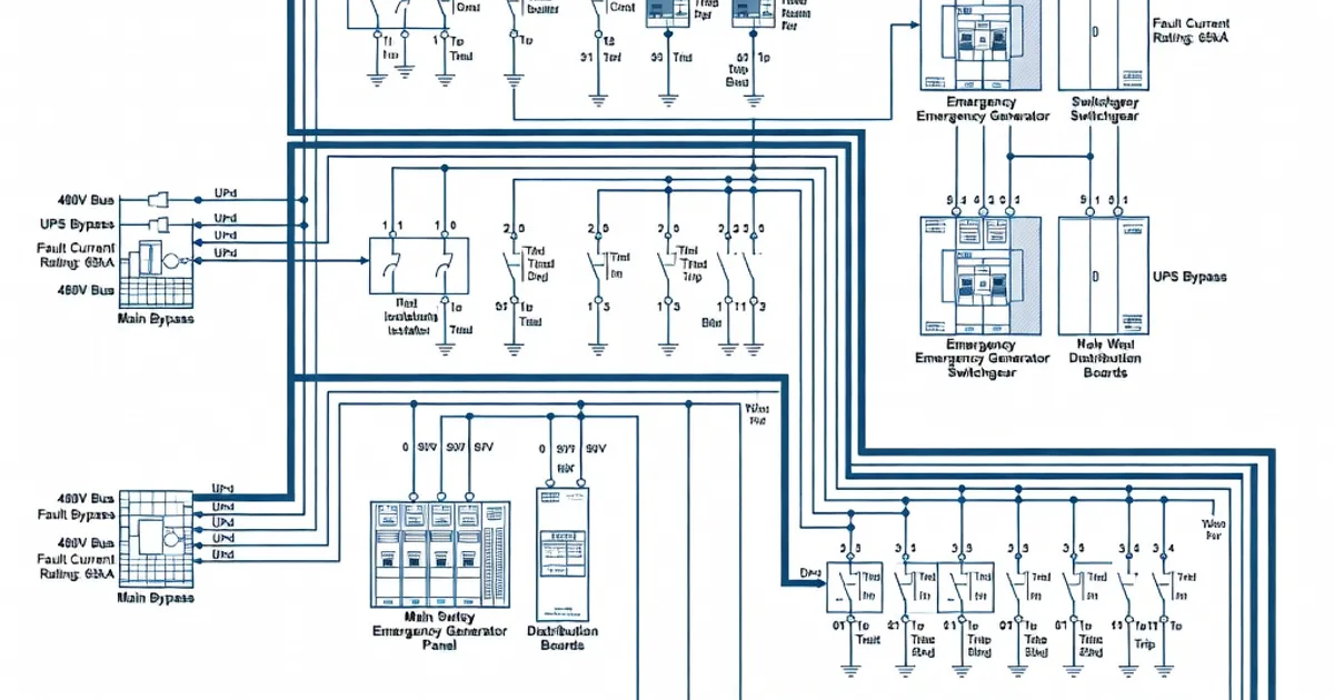
Redundancy, Segmentation and Selective Protection
To meet hospital uptime targets (often 99.99% for critical loads), distribution architecture uses redundancy and segmentation:
- Redundant sources: dual incoming feeds, automatic transfer switches (ATS) and generator sets with synchronous transfer to back up mains supply.
- Busbar segmentation: sectionalizing busbars to allow maintenance on a segment without interrupting other critical segments. For mains busbars that supply the whole switchboard, IEC 61439 guidance mandates using a diversity factor of 1.0 (no diversity) for the main bus rating where required by application [IEC 61439-2 Table 101].
- Selective coordination: protectors sized and time-coordinated so that only the nearest circuit protective device clears a fault, preserving supply to unaffected circuits.
- Redundant distribution paths: parallel feeders and dual final distribution panels for intensive care, operating rooms and imaging suites.
IEC 61439 encourages using rated diversity factors (RDF) for outgoing circuits per Table 101 in IEC 61439-2 but defaults to unity for mains and main busbars where no diversity may be applied in design verification [IEC 61439-2 Table 101].
Protective Devices, Coordination and Installation Best Practices
Protection and coordination in hospitals should align with the following practices:
- Place short-circuit protective devices (SCPDs) close to the busbar: SCPDs or main breakers should be within 3 m of busbar terminations to ensure that the bus and conductors are protected promptly in a fault [industry practice].
- Use RCDs for patient and staff safety: In applicable circuits, select Type A or Type B RCDs appropriate for medical device leakage and DC components in modern equipment.
- Implement thermal imaging and commissioning tests: perform thermal scans at load, verify torque settings, and confirm protective device settings for coordination with upstream protection.
- Derate for ambient conditions: where rooms exceed 35 °C, derate conductors and devices or provide climate control to meet the temperature-rise test assumptions of IEC 61439 (average ambient ≤35 °C) [IEC 61439-1 Clause 10.10].
Commissioning and Acceptance Tests
- Insulation resistance measurements between phases and earth.
- Continuity and polarity checks of protective conductors and neutral.
- Functional tests of transfer devices, ATS and automatic failure detection for IT systems.
- Verification of panel documentation and type-test certificates against installed configuration (Annex C of IEC 61439-1).
- Thermographic inspection under typical operating load to detect hotspots missed during type testing.
Specification Tables
The following table maps key IEC 61439 type-test clauses to the typical acceptance criteria designers and hospital electrical managers should demand in procurement specifications.
| IEC Clause / Test | Purpose | Typical Acceptance Criteria |
|---|---|---|
| Clause 10.10 — Temperature rise | Verify thermal performance at rated current | Test at rated current with declared RDF; average ambient ≤35 °C; temperature rise limits per manufacturer type-test report (no local hotspot beyond limits) |
| Clause 10.9 — Dielectric tests (power frequency / impulse Uimp) | Confirm insulation coordination and transients withstand | Power-frequency withstand and Uimp consistent with Overvoltage Category III (site-specific Uimp declared in documentation) |
| Clause 10.11 — Short-circuit | Verify mechanical and thermal withstand under prospective faults | Assembly SCCR rated to site prospective fault level; internal faults extinguish within test-specified timeframe (extinguish <30 s where applicable) |
| Clause 10.7 — Protective conductor continuity | Ensure low-impedance path for fault currents | High-current continuity checks show continuity to PE; resistance below manufacturer threshold |
| Clause 10.4 — Clearances & creepage | Prevent flashover and partial discharge | Clearances and creepage distances match declared insulation voltages; barriers used where required |
| Clause 10.12 — Degree of protection (IP) | Ingress protection for intended environment | IP code declared and validated per IEC 60529 (e.g., IP54 or higher for clinical zones) |
Manufacturer Examples and Product Selection
Major manufacturers supply IEC 61439-compliant assemblies tailored for hospitals. The table below summarizes selected vendor claims relevant to hospital procurement; verify each claim against current technical datasheets and type-test certificates supplied with the equipment.
| Brand | Product Example | Key Hospital Features |
|---|---|---|
| Siemens | NXPLUS C / Sentron | IEC 61439-2 compliant; options for IT/ITe systems, arc-resistant variants, integrated metering and building management interfaces [Siemens guide] |
| ABB | UniGear 500R / Ability panels | Double-insulation ready; RDF-optimised busbars; common IP54 options for cleanrooms; Uimp selections for Category IIIRelated Panel TypesFrequently Asked QuestionsRequest a QuoteTell us about your panel requirements and our engineering team will get back to you within 24 hours. Email Us [email protected]Call Us +90 232 332 22 78 |