Harmonic Mitigation in Panel Assemblies
Techniques for managing harmonics in panels with VFDs and non-linear loads.
Harmonic Mitigation in Panel Assemblies — Overview
Harmonic currents from non-linear loads (variable frequency drives, UPS, rectifiers, LED lighting, computer loads) materially affect the thermal, short-circuit and electromagnetic performance of low-voltage (LV) panel assemblies. IEC 61439 (parts 1 and 2) expressly addresses the consequences of unbalanced and harmonic currents and requires that manufacturers and specifiers account for them when they are significant. This article consolidates the relevant IEC requirements, practical mitigation techniques, verification and testing approaches, and industry product practices for IEC 61439-compliant panel assemblies. It draws on IEC normative guidance and published manufacturer application notes and white papers to provide a practical technical reference for panel designers, specifiers and project engineers.
Standards and Normative References
Designers must apply the current editions: IEC 61439-1:2020 (general rules) and IEC 61439-2:2020 (power switchgear and controlgear assemblies). Guidance for specifying assemblies appears in IEC/TR 61439-0:2022. Related standards that influence harmonic mitigation include IEC 60947 (switchgear device performance), IEC 61643-12 (surge protection), IEC 60529 (degrees of protection), and higher-voltage interfaces in IEC 62271 when LV assemblies interact with MV systems.
Key normative obligations and references:
- IEC 61439-1 Clause 1.3.1: Manufacturer and specifier must consider unbalanced and harmonic currents in design assumptions; where harmonics are significant (for example THD > 8%) the user must define the harmonic content and the manufacturer must verify the assembly accordingly.
- IEC 61439-1/-2: Temperature-rise verification (thermal calculation and/or test) must account for actual currents and losses; Table 101 (IEC 61439-2) provides rated diversity factors (RDF) used in current ratings and busbar loading.[1][2][6]
- IEC/TR 61439-0:2022: Provides guidance on specifying frequency tolerance, rated impulse withstand (Uimp), and how to document harmonic content as user information.[2][9]
- IEC 60947 series: Device performance can degrade under harmonic or low-frequency conditions; contactors and breakers may have reduced breaking capacity or altered thermal behavior if frequency departs from nominal.[3]
Why Harmonics Matter in IEC 61439 Panel Assemblies
Harmonic currents change how energy distributes in conductors and equipment:
- Higher RMS currents. Harmonics raise RMS current in phase and neutral conductors and in busbars, increasing I2R losses and temperature rise beyond what a purely sinusoidal load would cause. Without accounting for harmonics, temperature-rise verification may be invalid.
- Neutral overload. Triplen harmonics (3rd, 9th, etc.) are additive in the neutral of a three-phase four-wire system, potentially producing neutral currents greater than phase currents; IEC guidance treats neutral prospective short-circuit current above 60% of three-phase value as a condition requiring explicit rating and verification.[2]
- Degraded switching performance. Circuit-breaker and protective-device operation can change in presence of DC offset and high-frequency content (influencing Ipk and Icw behavior), so short-circuit verification must include realistic fault conditions where harmonics may cause time delays or device heating.[1][2]
- EMC and interference. Conducted emissions and immunity are affected by harmonic-rich outputs from VFDs and converters; assemblies must maintain EMC compatibility and equipotential bonding to avoid interference with nearby control equipment.[1]
- Surge and transient interaction. Harmonic-rich networks may encourage resonances and transient magnification; specify surge protective devices per IEC 61643-12 and ensure rated impulse withstand (Uimp) is adequate (Uimp commonly specified as Ui + 1200 V or as required by application).[1][2][3]
Quantitative Triggers and Thresholds
Practical thresholds to require special treatment:
- THD (Total Harmonic Distortion) > 8% — industry practice and IEC guidance indicate this level as a boundary where the user must specify harmonic content and the manufacturer must perform dedicated verification and possible derating or mitigation measures.
- Neutral prospective short-circuit current > 60% of three-phase value — neutral must be explicitly rated and tested rather than assumed within standard conditions.[2]
- Altitude > 2000 m — combine altitude derating with harmonic derating for temperature-rise and dielectric strength.
Design Mitigation Techniques
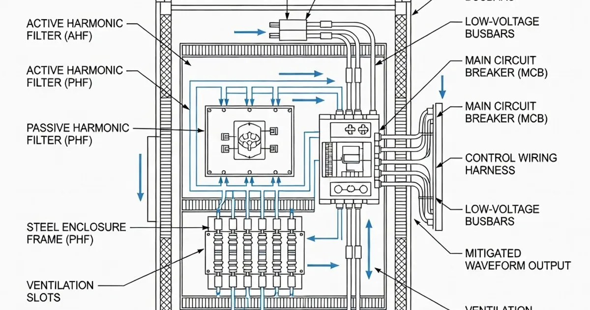
Mitigation reduces harmonic generation, isolates harmonics from bus systems, or increases assembly robustness to harmonics. Common industry techniques include:
- Oversized neutrals and busbars: Design neutral conductors and busbars for 100–200% of phase conductor capacity when significant 3rd harmonics are present. Many LV assembly manufacturers provide neutral bars rated up to 200% In specifically to handle triplen harmonic currents (see Siemens, Schneider product guidance).[1][3][4]
- Passive (detuned) reactors: Series reactors sized 7%–14% detuning reduce harmonic magnitudes by shifting the resonant frequency away from the dominant harmonic orders (common on VFD outputs). Typical detuned reactor rates are 7% (low impedance), 14% (higher attenuation) per manufacturer recommendations.[4][7]
- Active harmonic filters: Active filtering can reduce PCC THD to below 5%–8% depending on specification and harmonic order. Active filters adapt to load changes and are effective for medium and higher-order harmonics[3][6].
- Isolation transformers and phase-shifting transformers: Delta-wye or phase-shifting configurations can prevent certain harmonics from propagating into the main network.
- Selective placement and segregation: Use form of separation and enclosure IP/IK ratings (e.g., IP3XD for insulated enclosures) and ensure equipotential bonding; place harmonic-generating loads in dedicated compartments with appropriate ventilation and cooling.[5][6]
- Switchgear selection and coordination: Choose breakers and fuses with characteristic and breaking capacity proven under harmonic-rich conditions. Use gG or aM fuse types as appropriate for coordination under short-circuit with harmonic distortions.[5][7]
Verification, Testing and Calculation Requirements (IEC 61439)
IEC 61439 mandates specific verifications. Where harmonics are significant, these verifications must use realistic harmonic spectrums supplied by the user or defined in the project specification.
Temperature-rise Verification
IEC 61439 requires thermal verification (calculation or test) using rated currents and applied diversity factors (RDF). In presence of harmonics:
- Calculate conductor and device losses using harmonic-weighted RMS currents (I2R for fundamental and harmonic components).
- Account for additional losses in devices (transformers, reactors, circuit-breakers) due to harmonic-induced eddy and hysteresis losses; manufacturer data sheets often provide derating guidance for specified THD levels.[6]
- If THD > 8% or as specified, perform a full temperature-rise test under representative harmonic currents rather than relying on sinusoidal calculations only.
Short-circuit and Electrodynamic Verification
Short-circuit withstand (Icw, Ipk, Icc) must be verified according to IEC 61439 short-circuit clauses. Harmonics affect:
- Device let-through energy and peak current shape; coordinate protection devices with actual prospective short-circuit waveforms that include harmonic distortion and DC offset.
- Time-delayed device tripping caused by distorted currents; verify protective device characteristics under the expected waveform.
EMC and Dielectric Verification
Ensure the assembly meets EMC immunity and emission requirements. For dielectric verification, rated impulse withstand (Uimp) must consider transients possibly amplified by resonant harmonic conditions. IEC/TR 61439-0 provides guidance on frequency tolerance and Uimp specification (frequency tolerance typically 98–102% of fn for 50/60 Hz systems).[2][9]
Specification and Project Checklist
To avoid assumptions, include the following in every LV assembly specification when non-linear loads are present:
- Define harmonic spectrum (THD and individual harmonic orders expected) or require manufacturer measurements at design point.
- Specify maximum allowed THD at point of common coupling (PCC) — typical limits: <8% (trigger for special design) or <5% for stricter installations.
- Declare neutral prospective short-circuit current (as a percentage of three-phase) if above 60% or require oversized neutral.
- Indicate environmental conditions: altitude, ambient temperature, IP/IK rating, and ventilation approach.
- Require temperature-rise verification under specified harmonic spectrum and full routine tests per IEC 61439-1 Clause 11 before dispatch.[7]
- Specify required mitigation method(s): detuned reactors, active filters, oversized neutrals, or isolation transformers.
Industry Practices and Product Examples
Major manufacturers publish practical solutions for IEC 61439 panels used with VFDs and other non-linear loads.
| Manufacturer | Typical Harmonic Mitigation Features | Representative Specification/Notes |
|---|---|---|
| Siemens | Detuned reactors, harmonic filters, oversized neutral bars | Sentron/NXPLUS/8DJH series panels; neutral bars rated up to 200% In; Icw up to ~50 kA depending on model[1][8] |
| ABB | Active harmonic filters (REY), robust busbar systems, verified assemblies | UniGear ZS1 platforms with REY active filters reduce THD to <5–8%; application notes provide IEC 61439 verification guidance[3][6] |
| Schneider Electric | Integrated filters for VFD panels, oversized neutrals, IP-rated enclosures | Blokset / Okken solutions packaged for VFD bays; typical mitigation reduces THD to <8% for standard configurations[1][4][5] |
| Eaton | Passive detuned filters, high Ipk breakers | Power Xpert and associated filters (7%/14% reactors), some breakers rated Ipk 220 kA; follow manufacturer verification[7][8] |
Interpretation of Product Data
When reviewing product data sheets for assemblies intended to serve harmonic-generating loads, confirm:
- Manufacturer states thermal verification with the specified harmonic content (or performs test if requested).
- Icw and Ipk values are provided for relevant fault levels; check that device ratings are valid under distorted waveforms if available.
- Neutral bus rating and connection details — if neutrals are vulnerable to triplen harmonics, the product must list neutral capacity explicitly.
- Any included filtering is specified with guaranteed THD reduction at given load percentages (e.g., <5% at 100% load).
Mitigation Comparison: Passive vs Active Approaches
| Criterion | Passive (Detuned Reactors / Filters) | Active Harmonic Filters |
|---|---|---|
| Typical THD reduction | Partial (depends on tuning; effective for specific low orders) | High (can reduce THD to <5% across multiple orders) |
| Cost | Lower initial cost, simple maintenance | Higher upfront cost, software/controls require maintenance |
| Scalability | Fixed tuning; needs retuning or replacement for major load changes | Adaptive to changing loads; programmable |
| Power loss / efficiency | Low additional losses in well-designed reactors | Some losses from converter electronics; overall effective |
| Installation complexity | Lower; fits inline with VFD outputs or supply feeders | Higher; requires control integration and active cooling/space |
Practical Recommendations for Panel Designers
- Do not assume negligible harmonics. If VFDs or other converters are present, require the user to specify harmonic spectrum or measure at site conditions. Per IEC 61439-1 Clause 1.3.1, this is mandatory where harmonics are significant.[1][2]
- When in doubt, oversize neutrals and provide capacity on busbars for added thermal margin. Industry practice commonly uses neutral ratings from 100% up to 200% of phase rating when triplen harmonics are expected.[1][6]
- In specifications, require temperature-rise verification with harmonic-included waveforms and include routine testing per IEC 61439-1 Clause 11 prior to delivery.[7]
- Coordinate protection devices using manufacturer data for performance under distorted waveforms; where relevant, simulate short-circuit waveforms including harmonic content to validate breaker clearing times and let-through energy.[1][2][6]
- Consider upstream mitigation (active filters, detuned reactors) at the PCC rather than per-VFD solutions when multiple variable loads share a panel — this reduces system-wide THD and easing assembly verification burden.[3][6]
Documentation and Manufacturer Responsibilities
Under IEC 61439, the manufacturer must provide verification results and clearly state the assumptions used (ambient
Related Panel Types
Frequently Asked Questions
Request a Quote
Tell us about your panel requirements and our engineering team will get back to you within 24 hours.
Email Us
[email protected]Call Us
+90 232 332 22 78